Cullet crushing dust recovery device

A technology for dust recovery and broken glass, applied in glass recovery, recycling technology, grain processing, etc., can solve the problems affecting the health of operators in the workshop environment, the appearance of long glass pieces, and the process of jamming, so as to meet environmental protection requirements. requirements, improve the operating environment of workers, and achieve the effect of recycling

Pending Publication Date: 2021-04-20
信和光能(安徽)有限公司
View PDF3 Cites 0 Cited by
  • Summary
  • Abstract
  • Description
  • Claims
  • Application Information

AI Technical Summary

Problems solved by technology

However, when the existing equipment breaks broken glass, a large amount of dust will be generated, which will affect the workshop environment and the health of operators
Secondly, the dust produced by broken glass also contains glass powder. If it is not recycled, it will cause a waste of resources.
[0004] Furthermore, the current crusher uses the rotating shaft to drive the breaking hammer to rotate and break, and the breaking hammer is in the shape of a long strip; in the broken glass, there will be long strips of glass from time to time, which will cause jamming in the subsequent process

Method used


Image

  • Cullet crushing dust recovery device
  • Cullet crushing dust recovery device
  • Cullet crushing dust recovery device

Examples


Embodiment 1

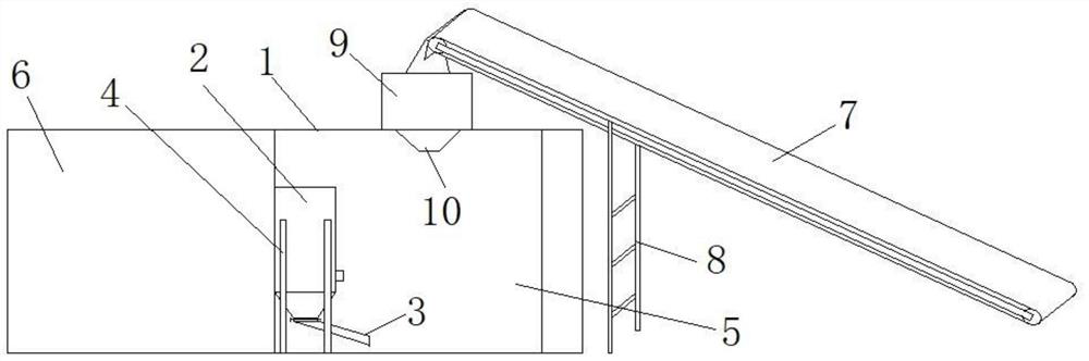
[0031] Such as Figure 1 to Figure 2 As shown, in this embodiment, the dust removal mechanism is a pulse bag filter 2 arranged on the inner side of the powder silo 1 . The pulse bag filter is composed of ash hopper, upper box, middle box, lower box and other parts. The upper, middle and lower boxes are divided into chambers. The exhaust channel of the bag filter extends out of the powder silo. When working, the dusty gas enters the ash hopper through the air inlet, the coarse dust falls directly into the bottom of the ash hopper, and the fine dust enters the middle and lower boxes upwards with the airflow turning, and the dust accumulates on the outer surface of the filter bag. The gas enters the upper box to the clean gas collection pipe-exhaust duct, and is exhausted to the atmosphere through the exhaust fan. The dust cleaning process is to cut off the air outlet duct of the room first, so that the bag in the room is in a state of no air flow (stop the air and clean the du...

Embodiment 2

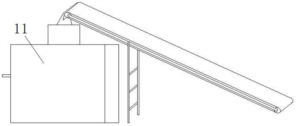
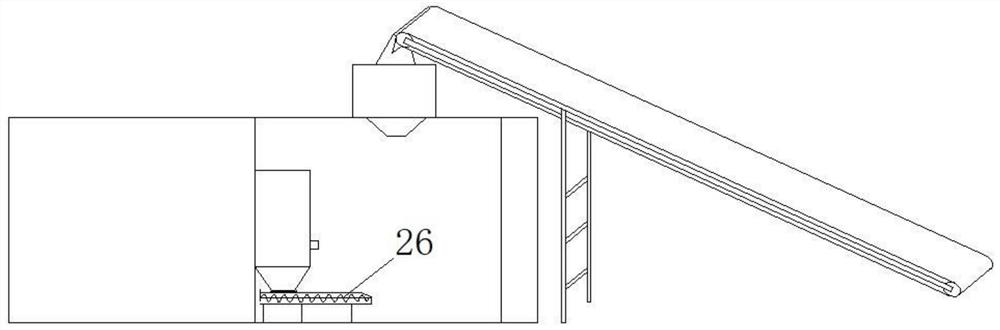
[0039] like Figure 3 to Figure 4 As shown, the difference between this embodiment and Embodiment 1 is that the bottom discharge port of the pulse bag filter 2 is connected to the screw discharge mechanism, and the discharge port of the spiral discharge mechanism points to the glass stockpile. The screw discharge mechanism adopts a screw conveyor, the feed port of the screw conveyor is connected with the bottom discharge port of the pulse bag filter, and the discharge port of the screw conveyor points to the glass stockpile. The screw conveyor is fixed on the carrier frame, and the carrier frame is fixed on the bottom surface of the powder silo. With this structure, the pulse bag filter can be directly installed on the screw conveyor, reducing the number of connecting parts between the pulse bag filter and the powder silo. , Reduce installation costs.

[0040] In this embodiment, the crushing mechanism includes a housing 12, a cylinder 13 disposed in the housing 12, and a cru...


PUM


Abstract

The invention provides a cullet crushing dust recovery device. The cullet crushing dust recovery device comprises a powder bin, a crushing mechanism is arranged on the powder bin, a discharging port of the crushing mechanism extends into the powder bin, the cullet crushing dust recovery device further comprises a feeding conveying mechanism used for conveying glass to a feeding port of the crushing mechanism, and a dust removal mechanism used for sucking in broken glass dust for treatment is arranged in the powder bin. The device can effectively eliminate the flying dust generated when cullet is broken, reduce the labor intensity of workers, improve the operation environment of the workers and meet the requirement for environmental protection treatment.

Description

technical field [0001] The invention relates to the technical field of glass production and processing, in particular to a broken glass dust recovery device. Background technique [0002] Glass is used more and more widely in today's society, but glass is a fragile product. Once it is broken, it will not be safe to continue to use. Therefore, it is necessary to deep crush and recycle some broken glass. [0003] Due to the technical requirements of glass production, large cullets cannot be directly added to the furnace for melting. If the large cullets are not further crushed, it will be difficult to melt after being added to the furnace, which will affect the product quality. Therefore, the large cullets must be crushed. However, when the existing equipment breaks broken glass, a large amount of dust will be generated, which will affect the workshop environment and the health of operators. Secondly, the dust produced by broken glass also contains glass powder, if not recycl...

Claims


Application Information

Patent Timeline
Patent Type & Authority Applications(China)
IPC IPC(8): B02C19/00B02C23/02B02C23/00B01D46/02B01D46/04
CPCY02W30/60
Inventor 赵遵庆刘琪
Owner 信和光能(安徽)有限公司
Why Eureka
Try Eureka