A method for pulling through the core of an extreme short-axis shoulder-pole beam motor

A technology of pole beam and short shaft is applied in the field of large motor installation and maintenance, which can solve the problems of lack of available space and small motor space in the workshop.

Active Publication Date: 2020-06-26
CHINA MCC20 GRP CORP
View PDF2 Cites 0 Cited by
  • Summary
  • Abstract
  • Description
  • Claims
  • Application Information

AI Technical Summary

Problems solved by technology

[0003] To sum up, although the driving in the workshop meets the requirements for motor core-piercing and hoisting, but the workshop space is narrow and the available positions for motor core-pumping (piercing) are lacking, the existing technology still has many deficiencies.

Method used


Image

  • A method for pulling through the core of an extreme short-axis shoulder-pole beam motor
  • A method for pulling through the core of an extreme short-axis shoulder-pole beam motor
  • A method for pulling through the core of an extreme short-axis shoulder-pole beam motor

Examples


Embodiment 1

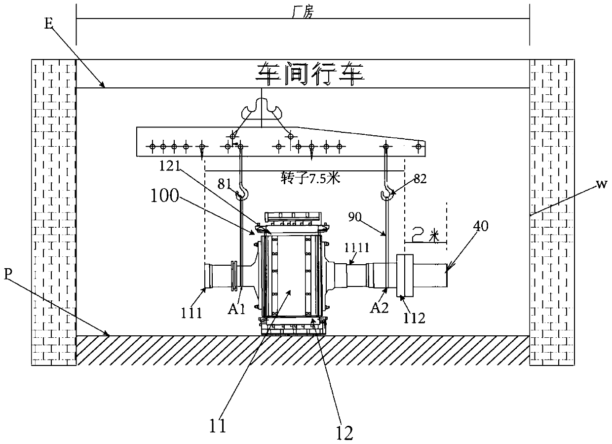
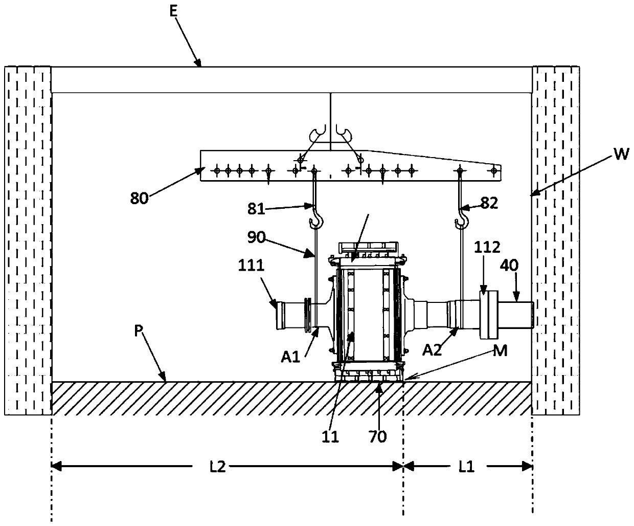
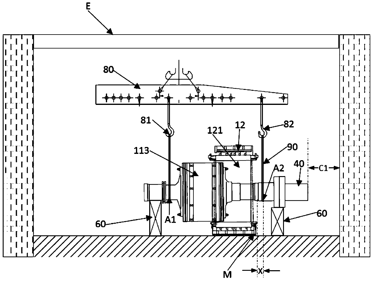
[0060] A preferred embodiment of the present invention, the method for pulling through the core of the extreme short-axis pole beam motor, see Figure 1-Figure 6 , which basically includes the following steps:

[0061] (1) Short shaft installation preparation: insert a buffer isolation plate (not shown) in the inner hole 121 of the stator 12 of the motor 100, so that the buffer isolation plate is interposed between the stator 12 and the rotor 11, preventing the rotor 11 from The inner hole 121 of the stator 12 is in direct contact with the hole wall; the two hoisting ropes 90 are respectively sleeved on the two hoisting points of the rotating shaft 1111 of the rotor 11, one hoisting point A1 is close to the motor collector ring 111, and the other hoisting point A2 is close to the rotor. The coupling 112 side is defined as the coupling side lifting point; the rotor 11 and stator 12 are integrally lifted to a core-pulling site P by using the workshop crane pole beam.

[0062] S...

Embodiment 2

[0080] Embodiment 2 is completely consistent with Embodiment 1 in the core pulling step. The only difference is that the short shaft installation preparation, short shaft installation, limit point selection, and overall lifting to the limit point in Embodiment 1 are changed to "limit point selection, overall lifting to the limit point, and short shaft installation" steps. This is because the selection of the limit point does not necessarily have to be carried out after the installation of the short shaft is completed. After the short shaft 40 of a certain specification and length is selected, it can be based on the actual situation of the core-pulling site. Just find the limit point M, then directly lift the motor 100 as a whole to the position of the limit point M, then connect the short shaft 40 to the shaft coupling 112 of the rotating shaft, and then perform the same first stage, Operation of the second stage and third stage core pulling steps. It is understandable that ...


PUM


Abstract

The invention provides a limit short-axis type core pulling and penetrating method for a shoulder-pole beam motor. The method comprises the following steps of stuffing a buffer isolation plate betweena motor stator and a motor rotor, and hoisting the entire motor to a core pulling site; installing and connecting a short shaft with a shaft coupling; selecting one limit point at the core pulling site, wherein the limit point is a reference for the placing position of the stator, the short shaft of the rotor gets close to a wall but does not press against the wall, and the distance between the limit point to another wall is much larger than the sum of the length of the stator, the length of the rotor and the length of the short shaft; integrally hoisting and moving the motor to the positionof the limit point; hoisting the motor by using a shoulder-pole beam of a shop traveler through adopting the tertiary core pulling mode and moving the motor towards a direction opposite to the limit point, wherein the position of one hoisting rope closer to a rotor coupling, one point in the short shaft and a position closer to the magnetic pole of the rotor are sequentially adopted as hanging points for continuously and horizontally moving the rotor in the relay mode. Therefore, the rotor is communicated with the short shaft to move together out of the stator, so that the core pulling is completed.

Description

technical field [0001] The invention belongs to the technical field of installation and maintenance of large motors, and in particular relates to a method for pulling through a core of an extreme short-axis pole beam motor. Background technique [0002] In the dismantling process of the large main drive motor, the method of extracting (threading) the core of the main motor is the most critical step, which is the most difficult, time-consuming and labor-intensive step. There are many methods for extracting (piercing) the core of the main motor of the rolling mill, but they are basically not applicable to the rough rolling motor of the hot rolling production line. The reason is that the rough rolling motor room is usually arranged in a place without a large crane, the space is narrow, and there are many unfavorable factors such as the lack of available sites for motor pumping (threading) cores. At present, for this type of motor, the usual construction method of core pumping ...

Claims


Application Information

Patent Timeline
Patent Type & Authority Patents(China)
IPC IPC(8): H02K15/00
Inventor 宋赛中李少星陈民泰金辽东
Owner CHINA MCC20 GRP CORP
Why Eureka
Try Eureka