
An image sensor and its output circuit

一种图像传感器、输出电路的技术,应用在图像传感器领域,能够解决时序控制复杂等问题,达到简化复杂度、宽动态范围的效果

Active Publication Date: 2019-11-12
HUAIAN XIDE IND DESIGN CO LTD
View PDF5 Cites 0 Cited by
  • Summary
  • Abstract
  • Description
  • Claims
  • Application Information

AI Technical Summary

Problems solved by technology

The disadvantage of this method is that the timing control of different exposure times is more complicated, and it also brings a larger circuit scale and area.

Method used


Image

  • An image sensor and its output circuit
  • An image sensor and its output circuit
  • An image sensor and its output circuit

Examples


Embodiment Construction

[0028] As described in the background technology section, at present, based on a frame of image captured, the method of controlling the use of different exposure times for the odd and even rows of the pixel array in the image sensor to obtain two sub-frame images and then merge them is implemented. While wide dynamic range imaging ranges, timing control is too complex.

[0029] The inventors of the present application have conducted research and analysis on the realization of wide dynamic range of image sensors in the prior art.

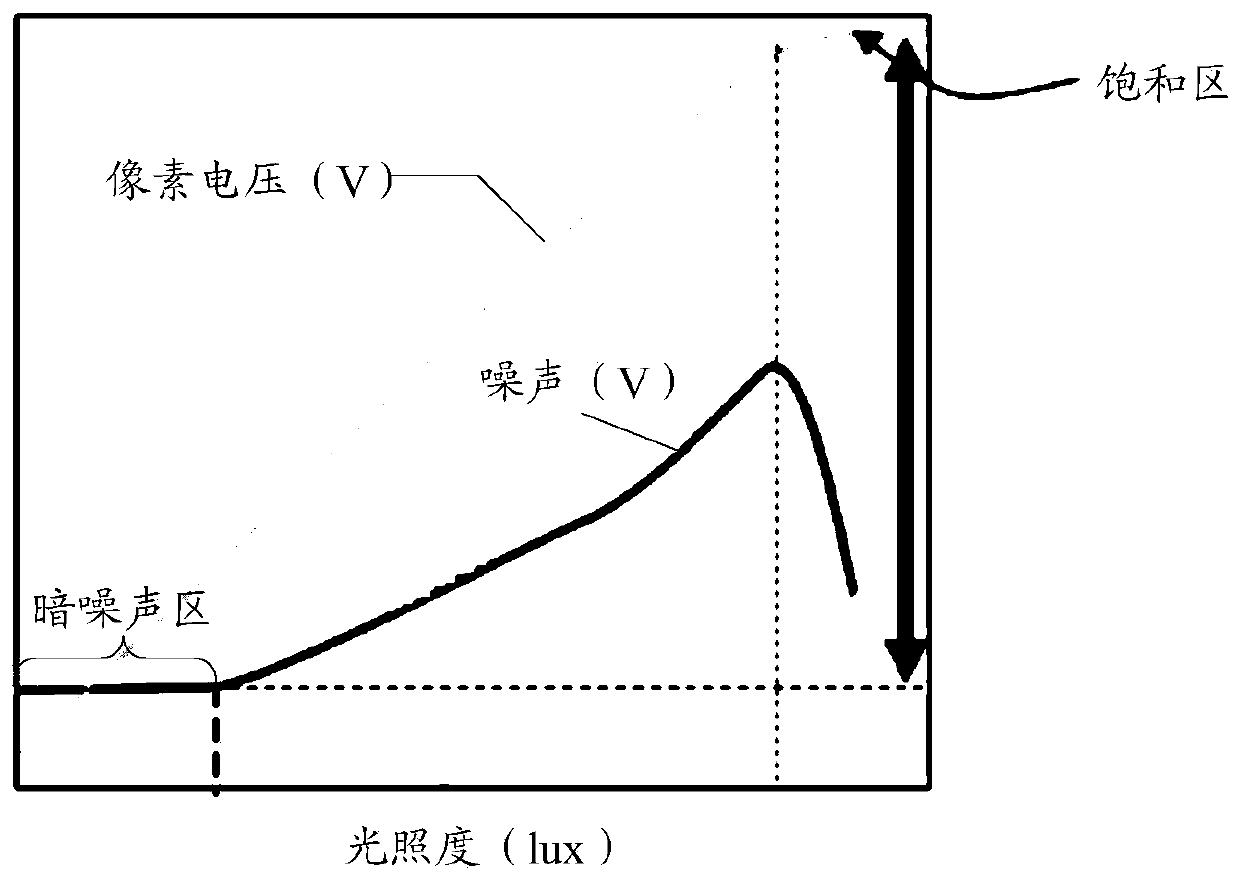
[0030] First, the image sensor needs to be exposed when capturing an image. The so-called exposure is to let the light shine on the photosensitive element to cause a series of physical and chemical changes, so as to obtain a frame of image. Specifically, when light hits a certain pixel on the image sensor (that is, the photosensitive element in the pixel circuit), charges are generated, and the amount of charges is proportional to the light received...


PUM


Abstract

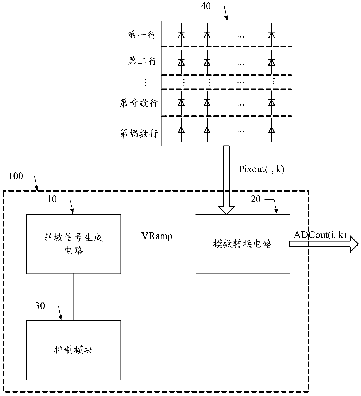
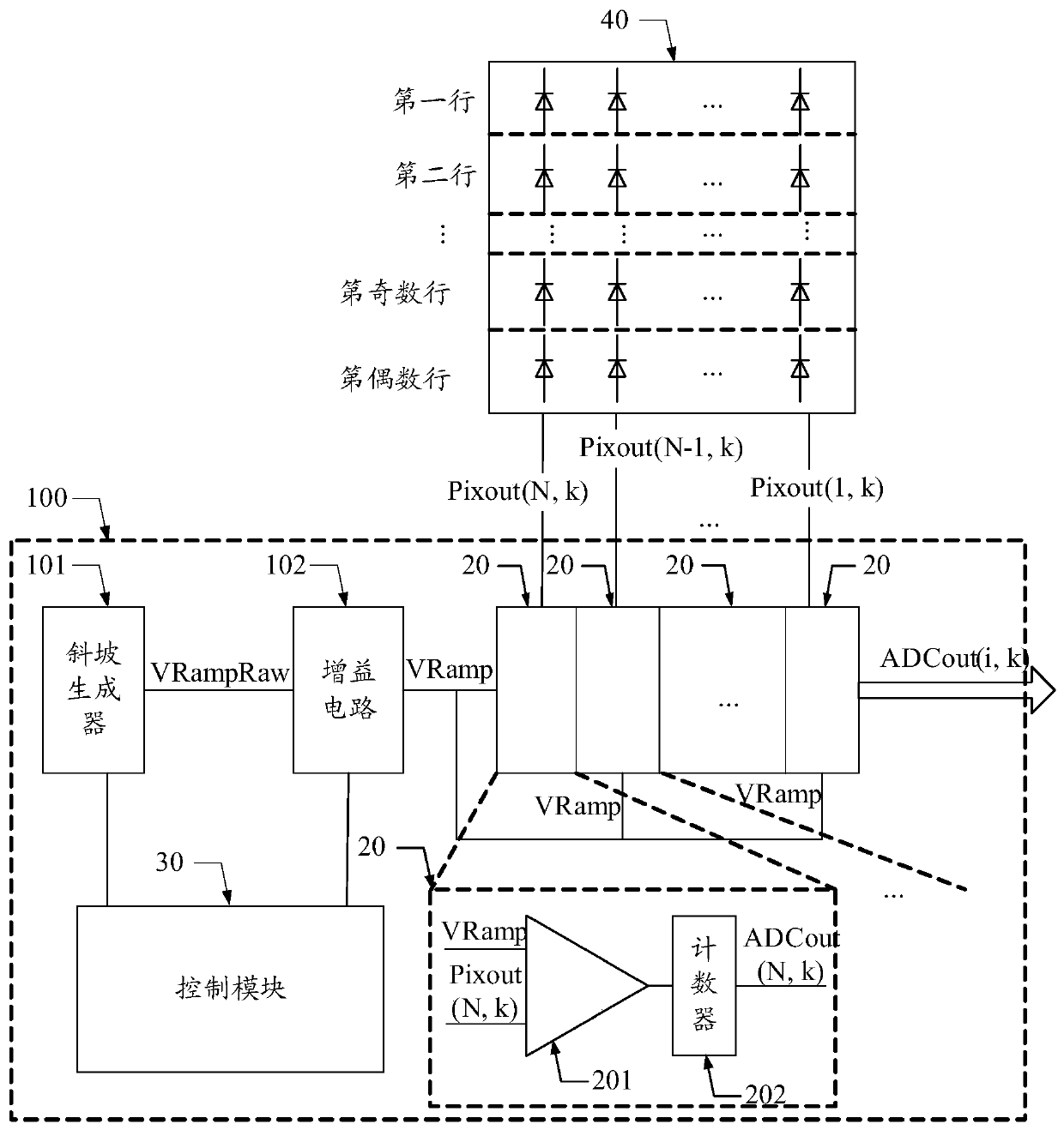
An image sensor and its output circuit, the output circuit includes: a slope signal generating circuit, adapted to output a slope voltage, the slope voltage changes linearly with time; an analog-to-digital conversion circuit, connected to the pixel voltage and the slope from the pixel array The voltage is adapted to obtain the pixel digital signal of the pixel voltage according to the moment when the pixel voltage is equal to the ramp voltage; the control module is adapted to control the ramp signal generation circuit to provide pixel voltages with Ramp voltages with different slopes. The adoption of the technical solution of the invention simplifies the complexity of controlling timing while realizing the wide dynamic range of the image sensor.

Description

technical field [0001] The invention relates to the technical field of image sensors, in particular to an image sensor and an output circuit thereof. Background technique [0002] The image sensor is an important part of the camera. In traditional cameras, the image sensor is realized by film, while in modern digital cameras, the image sensor is realized by Complementary Metal Oxide Semiconductor (CMOS for short) or Charge-coupled Device (CCD for short) image sensor to achieve. The pixel circuit is the core device of the image sensor to realize light sensing, and usually includes a photodiode to realize photoelectric conversion. The image sensor may also include a series of circuit modules for transmission, signal conversion and amplification, and control. In order to obtain excellent image quality in both strong and low light conditions, the researchers used every possible technique to increase the dynamic range of the image sensor pixels. [0003] At present, both high...

Claims


Application Information

Patent Timeline
Patent Type & Authority Patents(China)
IPC IPC(8): H04N5/225H04N5/235
CPCH04N23/54H04N23/741
Inventor 龚劲峰常建光
Owner HUAIAN XIDE IND DESIGN CO LTD
Learn More