
Hydraulic pipe orifice cleaning device

A technology for cleaning devices and pipelines, which is applied in the direction of cleaning hollow objects, cleaning methods and tools, grinding machines, etc. It can solve the problems of no protection, leakage, and labor and energy consumption of workers, so as to reduce physical exertion and improve cleaning efficiency , Improve the effect of cleaning effect

Active Publication Date: 2018-01-23
江苏华淼电子科技有限公司
View PDF5 Cites 7 Cited by
  • Summary
  • Abstract
  • Description
  • Claims
  • Application Information

AI Technical Summary

Problems solved by technology

[0002] At present, in the field of water conservancy, it is often necessary to use a large number of pipes to transport water resources. Commonly used PE pipes are usually connected to each other by welding. When storing water conservancy pipes, they are usually stacked directly without any protection. Dust and mud are often stuck to the mouth of the pipes. If there are pollutants such as dirt, it is usually necessary to wipe the mouth of the pipe before the welding operation, and the welding operation is performed directly without wiping the mouth of the pipe. Because the welding place contains pollutants such as mud, it is easy to cause the welding to not be tight, and the problem of pipeline leakage occurs. The burrs at the mouth due to wear will also affect the welding of the pipes. In the traditional water conservancy pipeline welding operation, it is necessary to wipe the pipe mouth with a rag to remove the surface sludge before welding, and then use sandpaper or grinding wheels to clean the worn parts. Grinding to remove burrs makes the surface smoother. Using this method will consume a lot of physical strength and energy of the workers when dealing with more pipes, and the surface burrs are removed by sandpaper or grinding wheels. The operators need to hold cleaning tools along the Rotate and clean the round axis of the nozzle. The strength of the hand has a great influence on the cleaning effect, and excessive strength will easily cause the surface of the nozzle to be uneven, which will affect the accuracy of the welding and fitting of the two pipes, and the problem of leakage will occur. Now the commonly used A pipeline nozzle cleaning device, such as the publication number CN205600063U, discloses a rotary scraper for cleaning the pipeline nozzle. The device supports the inside of the pipeline through the left and right support plates, scrapes the outer wall of the pipeline nozzle through the blade, and uses the device to clean the pipeline nozzle. When cleaning the mouth of the pipe, the operator needs to adjust and fix the device by hand during the process of adjusting the left and right support plates to support the inner wall of the pipeline. During the supporting process, it is necessary to constantly adjust the relative position between the blade and the pipe mouth. The positioning of the device depends entirely on the observation of the operator. Inaccurate positioning may easily cause a large distance between the scraper and the pipe mouth and incomplete cleaning, and the device can only clean the pipe. The outer ring is cleaned, and the pollutants at the pipe mouth and the inner wall of the pipe mouth cannot be cleaned, which has a serious impact on the subsequent welding operation. The device directly scrapes the pipe mouth without cleaning the debris first, and the sand contained in the debris is small. Particles have great damage to the scraper, and the use effect is not good

Method used


Image

  • Hydraulic pipe orifice cleaning device
  • Hydraulic pipe orifice cleaning device

Examples


Embodiment Construction

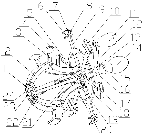
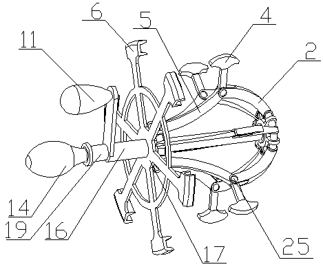
[0022] A water conservancy pipeline nozzle cleaning device of the present invention is realized in this way. When in use, the initial state of the transmission rod (2) and the connected pull rod (5) is stretched. When cleaning the nozzle of the water conservancy pipeline, first all Put the transmission rod (2) and all the pull rods (5) into the pipeline respectively, and make the U-shaped card slots on all the clamping blocks (6) respectively be stuck on the pipe nozzle, and the cleaning sheet on the wall of the U-shaped card slot ( 8) Fit the nozzle and the inner and outer walls, then hold the threaded sleeve (19) with one hand, and turn the fixed handle (14) with the other hand, because the threads on the surface of the threaded sleeve (19) and the fixed shaft (21) match , and the threaded sleeve (19) is fixed, and then the fixed shaft (21) moves out of the nozzle along the threaded sleeve (19), and drives the connecting ring (1) and auxiliary support ring (23) to move out of...


PUM


Abstract

The invention discloses a hydraulic pipe orifice cleaning device, in particular a device for cleaning pipe orifices and the inner and outer walls of the pipe orifices through internal support of hydraulic pipes and rotation of multiple clamping blocks along the pipe orifices. The hydraulic pipe orifice cleaning device is characterized in that a fixed handle is positioned at one end of a fixed shaft; a thread is arranged on the surface of the fixed shaft; a thread sleeve sleeves the fixed shaft, and is matched with a thread on the surface of the fixed shaft; a retainer ring sleeves one end of the thread sleeve; a rotating ring is positioned at the other end of the thread sleeve; a main support ring is connected with a rotating ring through multiple fixed lugs; the distances between two adjacent fixed lugs on the main support ring are the same; a connecting ring is positioned at the other end of the fixed shaft through a bearing; an auxiliary support ring is connected with the connectingring through multiple fixed lugs; the multiple fixed lugs on the auxiliary support ring are corresponding to the multiple fixed lugs on the main support ring one to one; one ends of multiple transmission rods are positioned on the auxiliary support ring at equal intervals; and one ends of the transmission rods are positioned between two adjacent fixed lugs on the auxiliary support ring.

Description

technical field [0001] The invention relates to a nozzle cleaning device of a water conservancy pipeline, which relates to a device for cleaning the nozzle of a water conservancy pipeline during building construction, and belongs to the field of water conservancy construction. In particular, it relates to a device for cleaning the nozzle and the inner and outer walls of the nozzle by internally supporting the water conservancy pipeline and cooperating with a plurality of clamping blocks to rotate along the nozzle. Background technique [0002] At present, in the field of water conservancy, it is often necessary to use a large number of pipes to transport water resources. Commonly used PE pipes are usually connected to each other by welding. When storing water conservancy pipes, they are usually stacked directly without any protection. Dust and mud are often stuck to the mouth of the pipes. If there are pollutants such as dirt, it is usually necessary to wipe the mouth of the...

Claims


Application Information

Patent Timeline
Patent Type & Authority Applications(China)
IPC IPC(8): B08B9/023B08B9/027B24B9/00B24B27/00
Inventor 朱元彩
Owner 江苏华淼电子科技有限公司
Learn More