

Speed reducer oil seal safety sleeving method
An oil seal and set technology, applied in the field of reducer oil seal safety set, can solve the problems of low probability of one-time success of oil seal set, low efficiency of oil seal set, poor concentricity, etc., to improve the success rate of one-time assembly, improve the efficiency of oil seal set, Avoid scratches and flanging effects
- Summary
- Abstract
- Description
- Claims
- Application Information
AI Technical Summary
Problems solved by technology
Method used
Image

Examples
Embodiment 1
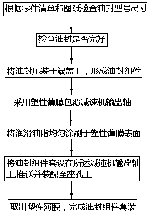
[0023] The method of safety assembly of reducer oil seal includes the following steps:
[0024] S1. Check the model size of the oil seal according to the parts list and drawings;
[0025] S2. Check whether the oil seal is intact;
[0026] S3. Use the gland to press-fit the oil seal on the end cover to form an oil seal assembly;
[0027] S4. Use plastic film to cover the output shaft of the reducer;
[0028] S5, evenly brushing lubricating grease on the surface of the plastic film;
[0029] S6. Sleeve the oil seal assembly on the output shaft of the reducer, through forward and reverse rotation and / or forward and backward swing
[0030] Push and assemble the oil seal assembly on the seat hole;
[0031] S7. Take out the plastic film to complete the oil seal assembly set.
[0032] The plastic film described in step S4 is a PE film.
[0033] The lubricating grease described in step S5 is glyceride.
[0034] The oil seal in step S1 is an oil seal with a dust-proof lip.
[0...
Embodiment 2
[0037] S1. Check the model size of the oil seal according to the parts list and drawings;
[0038] S2. Check whether the oil seal is intact;
[0039] S3. Use the gland to press-fit the oil seal on the end cover to form an oil seal assembly;
[0040] S4. Use plastic film to cover the output shaft of the reducer;
[0041] S5, evenly brushing lubricating grease on the surface of the plastic film;
[0042] S6. Sleeve the oil seal assembly on the output shaft of the reducer, through forward and reverse rotation and / or forward and backward swing
[0043] Push and assemble the oil seal assembly on the seat hole;
[0044] S7. Take out the plastic film to complete the oil seal assembly set.
[0045] The plastic film described in step S4 is a PP film.
[0046] The lubricating grease described in step S5 is calcium-based lubricating grease.
[0047] The oil seal in step S1 is an oil seal with a dust-proof lip.
[0048] The number of oil seals in step S1 is 2, and the 2 oil seals a...
Embodiment 3
[0050] S1. Check the model size of the oil seal according to the parts list and drawings;
[0051] S2. Check whether the oil seal is intact;
[0052] S3. Use the gland to press-fit the oil seal on the end cover to form an oil seal assembly;
[0053] S4. Use plastic film to cover the output shaft of the reducer;
[0054] S5, evenly brushing lubricating grease on the surface of the plastic film;
[0055] S6. Sleeve the oil seal assembly on the output shaft of the reducer, through forward and reverse rotation and / or forward and backward swing
[0056] Push and assemble the oil seal assembly on the seat hole;
[0057] S7. Take out the plastic film to complete the oil seal assembly set.
[0058] The plastic film described in step S4 is a PE film.
[0059] The lubricating grease described in step S5 is aluminum-based lubricating grease.
[0060] The oil seal in the step S1 is an oil seal with a dust-proof lip.
[0061] The number of oil seals in the step S1 is 2, and the 2 oi...
PUM
 Abstract
Description
Claims
Application Information