
Frame automatic locking device for forming machine

An automatic locking and molding machine technology, applied in the direction of ceramic molding machines, supply devices, auxiliary molding equipment, etc., can solve the problems of troublesome and unsafe locking and separation processes, and achieve the goal of eliminating potential safety hazards, ensuring accurate positioning, and accurate positioning Effect

Pending Publication Date: 2018-01-23
BEIJING LONGXIANG ENVIRONMENT PROTECTION TECH CO LTD
View PDF0 Cites 0 Cited by
  • Summary
  • Abstract
  • Description
  • Claims
  • Application Information

AI Technical Summary

Problems solved by technology

Since the locking and separation between the two frames is achieved by manual insertion and removal of taper pins by workers, the entire locking and separation process is very troublesome, and the workers are too close to the machine, which is very unsafe

Method used


Image

  • Frame automatic locking device for forming machine
  • Frame automatic locking device for forming machine
  • Frame automatic locking device for forming machine

Examples


Embodiment Construction

[0019] The frame automatic locking device for forming machine of the present invention will be further described in detail in conjunction with the accompanying drawings and specific embodiments:

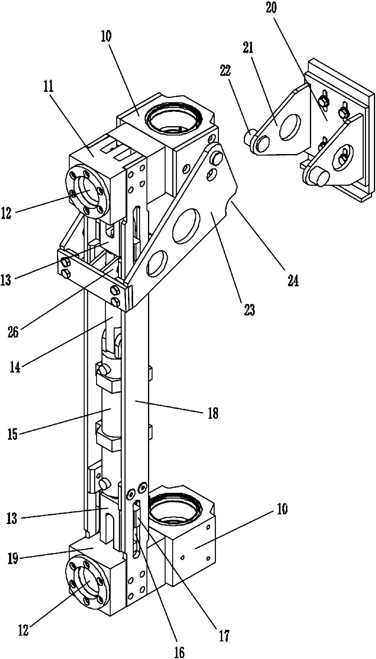
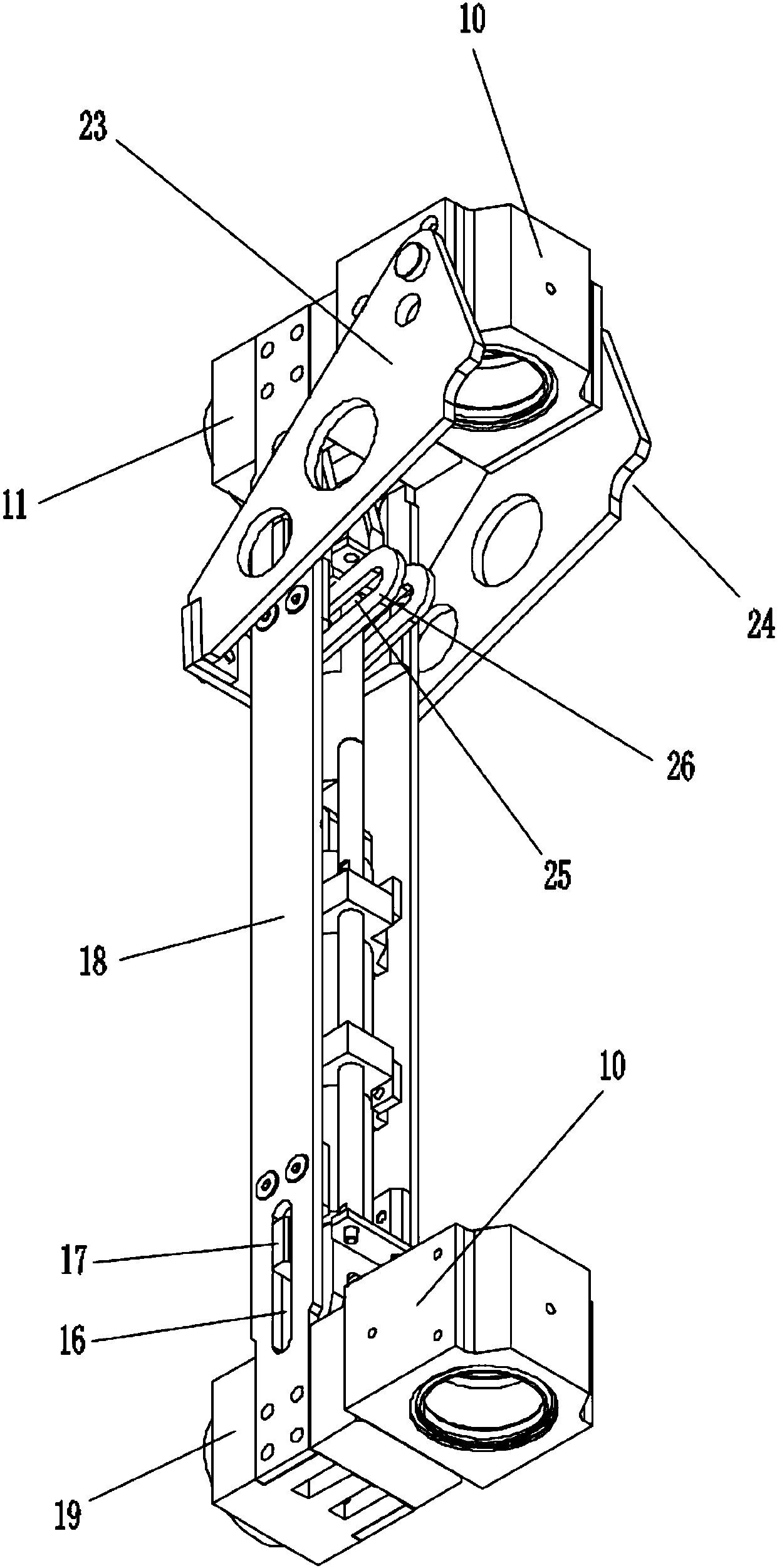
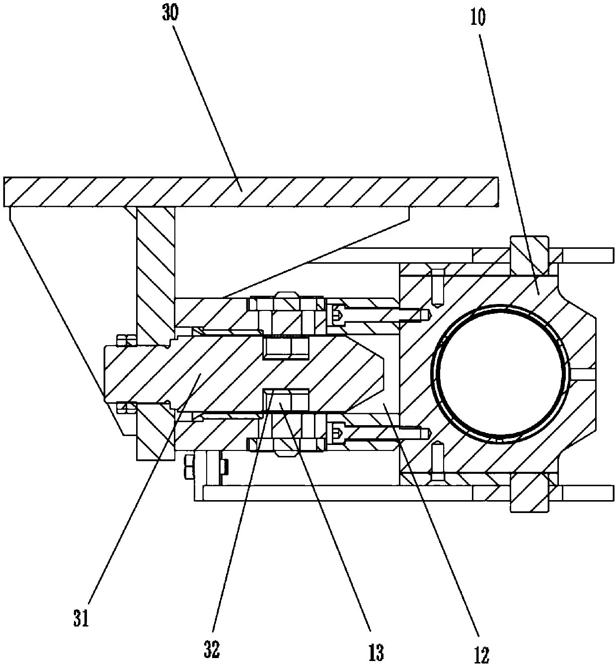
[0020] Such as figure 1 , figure 2 and image 3 As shown, in this specific embodiment, the frame automatic locking device for molding machine of the present invention includes a guide sleeve 10 for being installed on the guide column of the intermediate frame forming part, and also includes an upper plug block 11, a lower plug block 19, A plug 13 for inserting into the cavity of the upper plug block 11 and the lower plug block 19 and a driving device 15 for controlling the expansion and contraction of the plug 13 . Drive unit 15 specifically adopts oil cylinder (certainly also can adopt air cylinder), and oil cylinder is electrically connected with controller by electromagnetic valve, and its piston rod 14 is connected with plug 13, and the elongation and shortening of piston rod...


PUM


Abstract

A frame automatic locking device for a forming machine comprises guide sleeves used for being mounted on a guide column of a middle frame forming part. Connecting plates are arranged between the two guide sleeves. The frame automatic locking device further comprises an upper inserting block, a lower inserting block, inserting heads used for being inserted into an inner cavity of the upper inserting block and an inner cavity of the lower inserting block and a drive device used for controlling the inserting heads to stretch out and draw back. The drive device is electrically connected with a controller. The upper inserting block and the lower inserting block are mounted on the two guide sleeves correspondingly. The connecting plates are mounted between the upper inserting block and the lowerinserting block. Pin holes allowing pins to be inserted are formed in the side wall of the upper inserting block and the side wall of the lower inserting block. The pins are mounted on a face material feeding frame part. Inserting portions allowing the inserting heads to be inserted so as to prevent the pins from being separated out from the pin holes are arranged on the pins. According to the frame automatic locking device, through mutual cooperation of an oil cylinder, the inserting heads, the pins, the upper inserting block and the lower inserting block, automatic locking and separating ofthe face material feeding frame part and the middle frame forming part are achieved, convenience and rapidness are achieved, and the aim can be achieved by pressing a button without personnel approaching.

Description

technical field [0001] The invention relates to a molding machine, in particular to a frame automatic locking device for a molding machine. Background technique [0002] We know that the forming machine is generally composed of the middle frame forming part, the fabric feeding frame part and the base material feeding frame part, and the mold of the product is usually installed on the middle frame forming part. In order to facilitate the installation of the mold, it is necessary to separate the forming part of the middle frame from the feeding frame part of the fabric, so that there is a space between the two. After the mold is installed in the forming part of the middle frame, reset the feeding frame part of the fabric. [0003] At present, most manufacturers design the intermediate frame forming part and the fabric feeding frame part as a detachable movable structure that is convenient to open and close, specifically: Figure 4 As shown, a guide post 100 is installed on the...

Claims


Application Information

Patent Timeline
Patent Type & Authority Applications(China)
IPC IPC(8): B30B15/04B30B15/30B28B13/02B28B17/00
Inventor 闫慧文
Owner BEIJING LONGXIANG ENVIRONMENT PROTECTION TECH CO LTD
Learn More