

Slope paver
A paver and slope technology, applied in the field of slope paver, can solve the problems of labor consumption and poor paving quality, and achieve the effect of solving the labor consumption
- Summary
- Abstract
- Description
- Claims
- Application Information
AI Technical Summary
Problems solved by technology
Method used
Image

Examples
Embodiment Construction
[0036] The present invention will be described in detail below in conjunction with the accompanying drawings and embodiments.
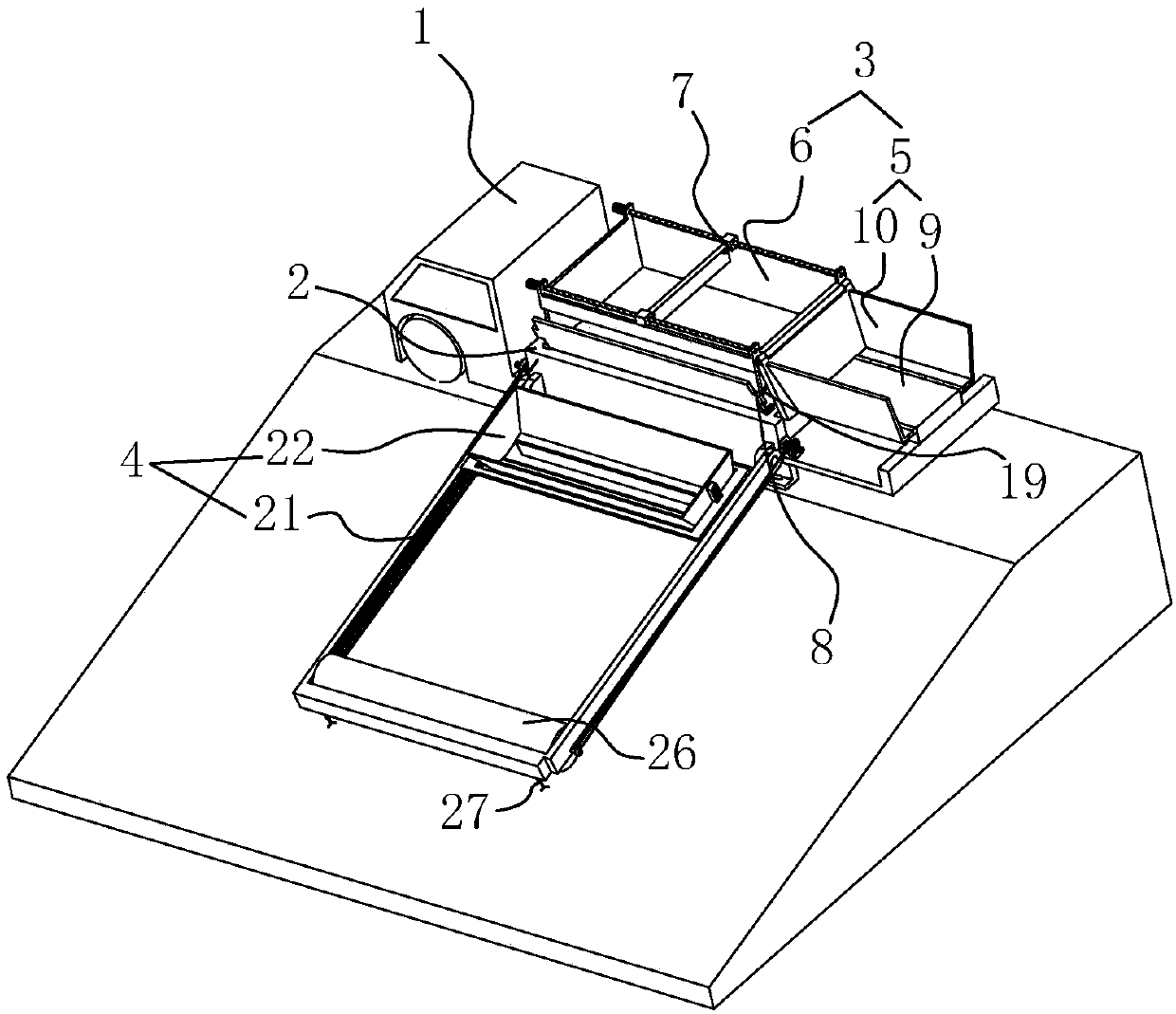
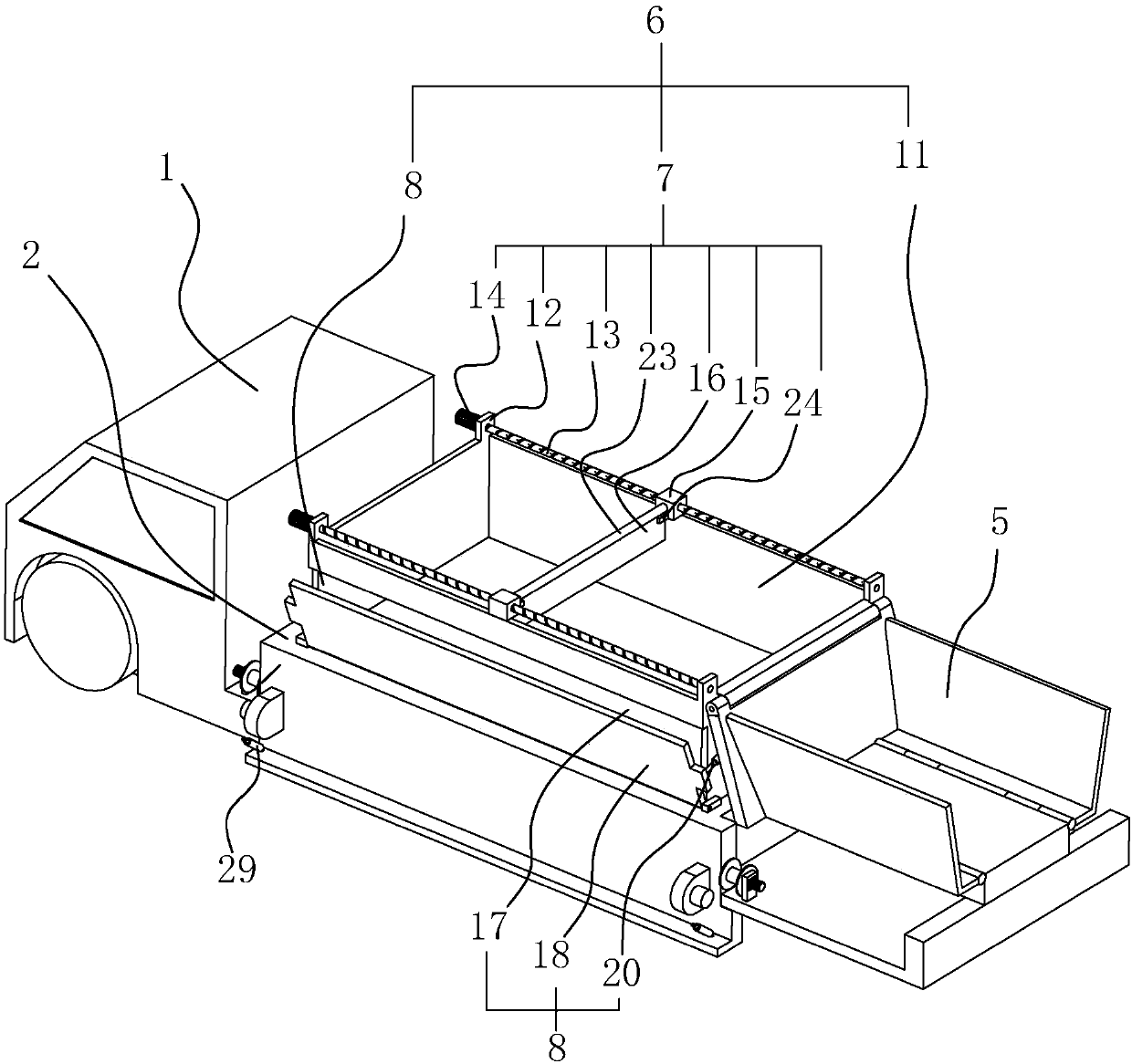
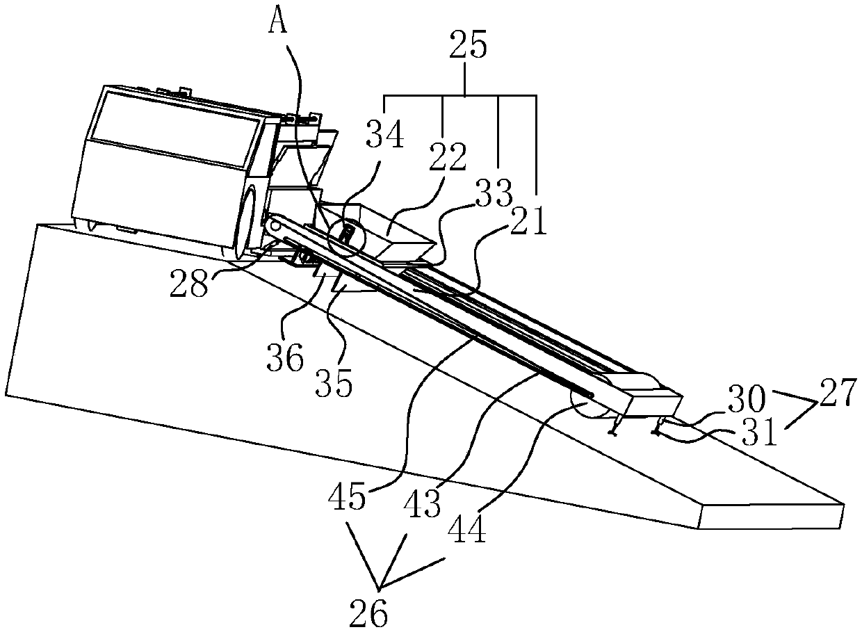
[0037] A slope paver such as figure 1 As shown, including the car body 1, a platform 2 is also arranged at the rear of the car body 1, a batching mechanism 3 is arranged on the platform 2, and a paving mechanism 4 is arranged on one side of the batching mechanism 3. After the materials are poured into the batching mechanism 3, the materials are evenly distributed in the batching mechanism 3 through the batching mechanism 3, and then the materials in the batching mechanism 3 are directly poured into the paving mechanism 4, and the slope is paved by the paving mechanism 4.
[0038] Such as figure 1 As shown, the batching mechanism 3 includes a first material receiving device 5 arranged at the rear of the platform 2, the first material receiving device 5 includes a base plate 9 hinged at the rear end of the platform 2, and a cylinder is arranged between...
PUM
 Abstract
Description
Claims
Application Information