Eddy current displacement sensor array space geometry calibration method

A displacement sensor and geometric calibration technology, which is applied in the detection field, can solve the problems that there are few methods for spatial geometric calibration of eddy current displacement sensor arrays, no universality, and unsatisfactory

Active Publication Date: 2018-01-23
DALIAN UNIV OF TECH
View PDF12 Cites 10 Cited by
  • Summary
  • Abstract
  • Description
  • Claims
  • Application Information

AI Technical Summary

Problems solved by technology

[0003] The invention patent publication number applied by Wang Yongqing and others of Dalian University of Technology is CN104279946B, "A Calibration Method for Spherical Displacement Measurement of Eddy Current Sensor", which proposes to use calibration data to establish a calibration surface for spherical displacement measurement of eddy current displacement sensor. This method can realize Calibrate the output of the displacement measurement value of any curvature spherical surface, but it is only suitable for the spatial calibration of an eddy current displacement sensor. It cannot calibrate the spatial geometric position of the array of eddy current displacement sensors, and it is only suitable for the measurement and calibration of the spherical surface. There is no universality
In "Static Automatic Calibration of Displacement Sensors and Analysis of Test Results" published by Ding Meiying and others in the third issue of Sensor World Journal in 2010, the automatic calibration system was used to replace the manual static calibration method to achieve calibration. Although this method can improve the calibration efficiency, it only Can be calibrated for the characteristic function of a single eddy current displacement sensor, but cannot be calibrated for its spatial geometric position
It is found that there are very few studies on the spatial geometry calibration of eddy current displacement sensor arrays, which cannot meet the needs of the current detection field for the overall spatial geometry calibration of eddy current displacement sensor arrays. There are few calibration methods

Method used


Image

  • Eddy current displacement sensor array space geometry calibration method
  • Eddy current displacement sensor array space geometry calibration method
  • Eddy current displacement sensor array space geometry calibration method

Examples


Embodiment Construction

[0035] The specific embodiments of the present invention will be described in detail below in conjunction with the technical solutions and accompanying drawings.

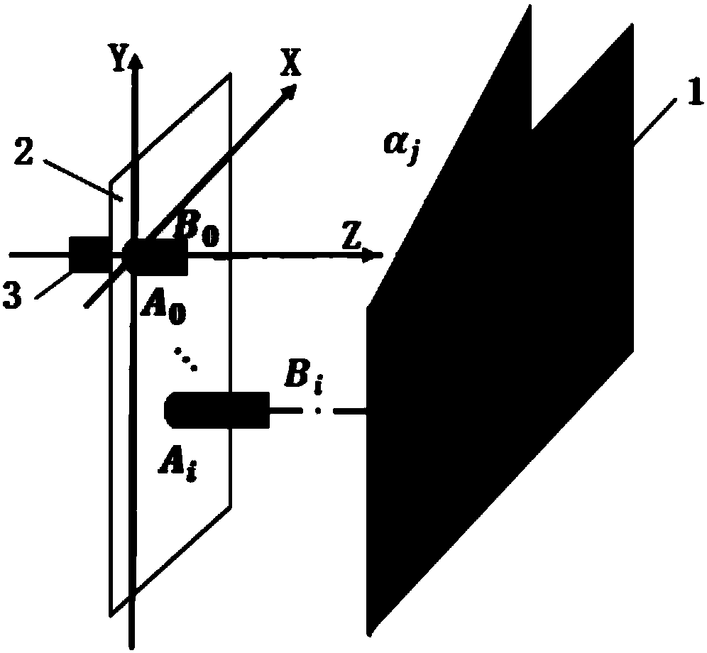
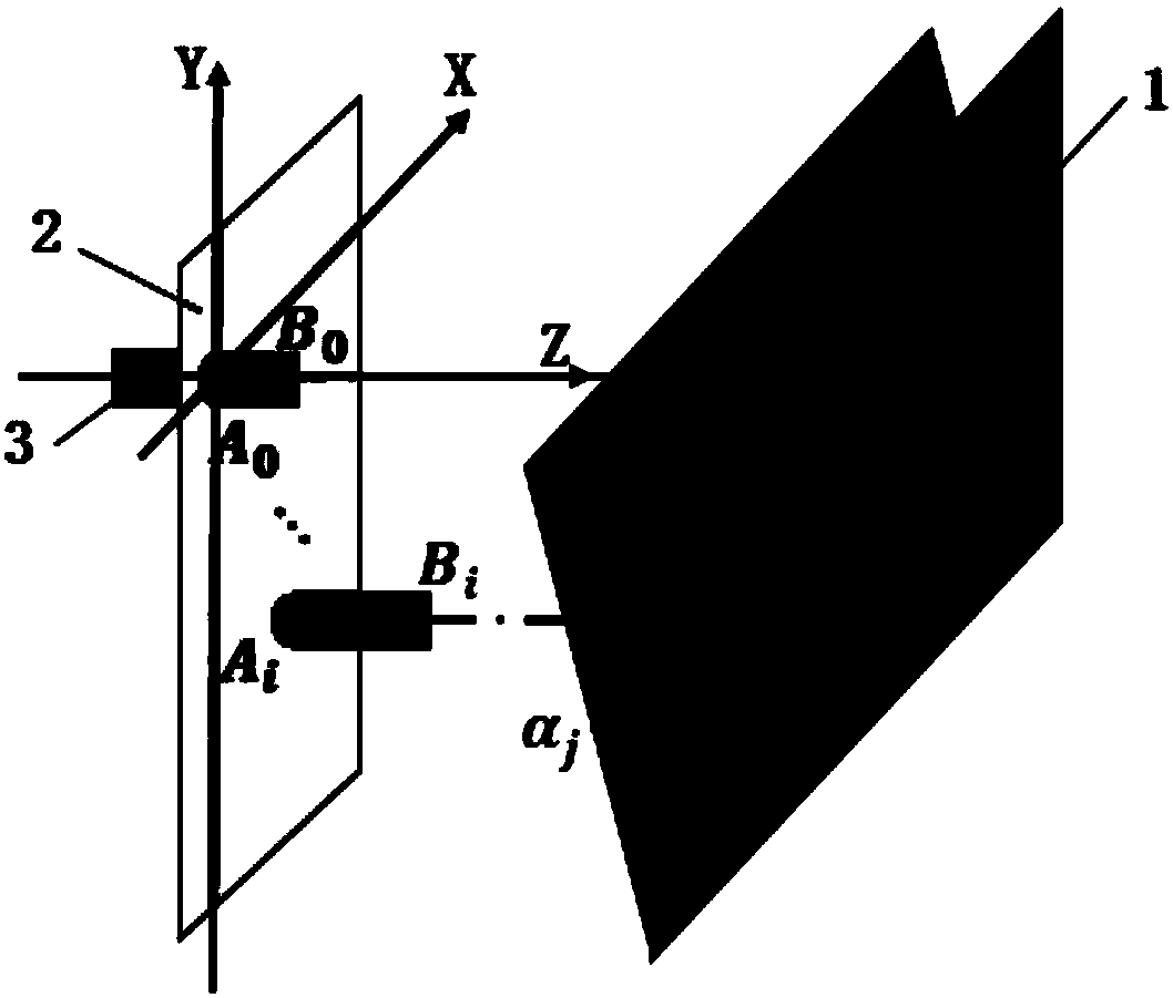
[0036] Figure 5 The overall flowchart for the spatial geometry calibration of the eddy current displacement sensor array. The whole calibration process includes two steps: the space geometry calibration of the XOZ projection surface of the eddy current displacement sensor array and the space geometry calibration of the YOZ projection surface of the eddy current displacement sensor array. The first step is that the probe is aligned with the plane calibration plate, and the plane calibration plate is controlled to rotate multiple times along a horizontal edge, and the rotation angle and the degree of the eddy current displacement sensor are read each time, and the two-axis directions of any two probes in the eddy current displacement sensor array are compared. To achieve spatial geometry calibration, the second step...


PUM


Abstract

The invention belongs to the detection technical field and relates to a space geometry calibration method for any eddy current displacement sensor array by utilizing a common plane calibration board.The method is characterized by, to begin with, through rotation of the plane calibration board along one edge, realizing space geometry calibration in two directions between any two probes in an eddycurrent displacement sensor array; then, through rotation of the plane calibration board along the other edge, realizing space geometry calibration in the third direction of the any two probes; and finally, realizing space geometry calibration of the eddy current displacement sensor array, and obtaining space three-dimensional information of any probe in the array. The method realizes overall space geometry calibration of the eddy current displacement sensor array through two-axis rotation of the calibration board, thereby eliminating installation and processing errors, and improving calibration precision effectively; and the method is high in universality.

Description

technical field [0001] The invention belongs to the technical field of detection, and relates to a space geometry calibration method for an arbitrary eddy current displacement sensor array by using an ordinary plane calibration plate. Background technique [0002] Since the eddy current displacement sensor is based on Faraday's electromagnetic induction principle, it uses the eddy current effect to achieve non-contact, high linearity, and high resolution measurement of the distance between the measured metal conductor and the probe surface. Nowadays, it is more and more used in the field of measurement. In addition, the use of eddy current displacement sensors is no longer limited to a single use to measure displacement and small changes in displacement, but more and more eddy current displacement sensor arrays formed by multiple eddy current displacement sensors are used. To further realize the conversion from one-dimensional displacement value to three-dimensional spatial ...

Claims


Application Information

Patent Timeline
Patent Type & Authority Applications(China)
IPC IPC(8): G01B7/02
Inventor 刘巍王婷梁冰周孟德贾振元
Owner DALIAN UNIV OF TECH
Why Eureka
Try Eureka