
MEMS inertial measurement unit with crossing axis coupling error compensation

An inertial measurement unit and coupling error technology, which is applied in the field of MEMS inertial navigation, can solve problems affecting the output accuracy of the system, and achieve the effects of improving output accuracy, easy maintenance, and low power consumption

Active Publication Date: 2017-10-20
SOUTHEAST UNIV
View PDF4 Cites 4 Cited by
  • Summary
  • Abstract
  • Description
  • Claims
  • Application Information

AI Technical Summary

Problems solved by technology

[0004] Affected by processing technology and installation, MEMS inertial measurement units will have cross-axis coupling errors, which seriously affect the output accuracy of the system. Therefore, establishing a cross-axis coupling model to compensate for errors is also the focus of MEMS inertial measurement unit development technology

Method used


Image

  • MEMS inertial measurement unit with crossing axis coupling error compensation
  • MEMS inertial measurement unit with crossing axis coupling error compensation
  • MEMS inertial measurement unit with crossing axis coupling error compensation

Examples


Embodiment Construction

[0020] The embodiments of the present invention are described in detail below, and examples of the embodiments are shown in the accompanying drawings. The following embodiments described with reference to the accompanying drawings are exemplary, and are only used to explain the present invention, and cannot be construed as limiting the present invention.

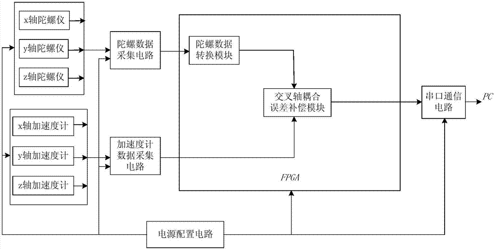
[0021] A MEMS inertial measurement unit with cross-axis coupling error compensation, such as figure 1 Shown. Including 3 single-axis MEMS gyroscopes and their signal acquisition circuits for measuring 3 axial angular velocity information, 3 single-axis MEMS accelerometers and their signal acquisition circuits for measuring 3 axial acceleration information, gyro data conversion module, cross-axis Coupling error compensation module, serial communication circuit, host computer, power configuration circuit.

[0022] The three axial single-axis gyroscopes are all analog output MEMS gyroscopes, and the signal acquisition circuit (tha...


PUM


Abstract

The invention discloses an MEMS inertial measurement unit with crossing axis coupling error compensation. The MEMS inertial measurement unit comprises three axial MEMS analog output gyroscopes and signal collecting circuits thereof, three axial MEMS digital output accelerometers and signal collecting circuits thereof, a gyroscope data conversion module, a crossing axis coupling error compensation module, a serial port communication circuit and a power supply configuration circuit, wherein the three axial MEMS analog output gyroscopes and the signal collecting circuits thereof are used for realizing the collection of gyroscope signals; the three axial MEMS digital output accelerometers and signal collecting circuits thereof are used for realizing the collection of accelerometer output signals; the gyroscope data conversion module is used for realizing the analog-digital conversion of the gyroscope data; the crossing axis coupling error compensation module is used for realizing the data treatment for the analog output gyroscopes and the digital output accelerometers; the serial port communication circuit is used for realizing the communication with an upper computer; the power supply configuration circuit is used for supplying various power supplies to the whole measurement unit. The MEMS inertial measurement unit not only can realize the collection of the carrier six-axis position information but also can eliminate the crossing axis coupling error caused by processing and mounting.

Description

Technical field [0001] The invention relates to a MEMS inertial measurement unit with cross-axis coupling error compensation, belonging to the technical field of MEMS inertial navigation. Background technique [0002] With the development of technology, the accuracy of MEMS inertial measurement unit is continuously improved, and because of its small size, low power consumption, and low cost, it has been widely used in more and more fields. The development of MEMS inertial measurement unit has extremely high value to the national economy and national defense construction. [0003] The first MEMS inertial measurement unit was launched in 1994 by the Draper laboratory in the United States. With the continuous advancement of technology, the integration of MEMS inertial measurement units is getting higher and higher, the volume is gradually decreasing, and the accuracy is getting higher and higher. The products that have been commercialized at present mainly include the HG-1910 of Hone...

Claims


Application Information

Patent Timeline
IPC IPC(8): G01C21/18G01C25/00
CPCG01C21/18G01C25/005
Inventor 李宏生邵安成吕正黄丽斌
Owner SOUTHEAST UNIV
Learn More