Shielded open loop type magnetic gathering ring-free tunneling magnetoresistive sensor

A technology of tunnel magnetoresistance and tunnel magnetoresistance, which is applied in the field of magnetic sensors, can solve the problems of inaccurate output, decrease of magnetic gathering ability of current sensor magnetic core, limitation of current sensor use and test environment, etc., so as to improve output accuracy and output The effect of accuracy and noise immunity

Inactive Publication Date: 2014-01-01
SHANGHAI FREESOR ELECTRONICS CO LTD
View PDF11 Cites 14 Cited by
  • Summary
  • Abstract
  • Description
  • Claims
  • Application Information

AI Technical Summary

Problems solved by technology

When the current passes through the conductor perpendicular to the external magnetic field, a potential will appear between the two end faces of the conductor perpendicular to the magnetic field and the current direction. The traditional Hall open-loop current sensor generates the current flowing through the measured conductor through the magnetic gathering ring. The magnetic field is gathered in the magnetic ring with a gap, and the Hall sensing chip is placed in the gap of the magnetic gathering ring. The magnetic field in the gap passes through the Hall sensing chip vertically, and a Hall potential difference is generated at both ends of the sensing chip. Through subsequent amplification The circuit increases the induction signal, and the output signal changes linearly when the current c

Method used


Image

  • Shielded open loop type magnetic gathering ring-free tunneling magnetoresistive sensor
  • Shielded open loop type magnetic gathering ring-free tunneling magnetoresistive sensor
  • Shielded open loop type magnetic gathering ring-free tunneling magnetoresistive sensor

Examples


Example Embodiment

[0015] The technical solutions of the present invention will be further explained below in conjunction with the drawings and embodiments, but the following content is not used to limit the protection scope of the present invention.

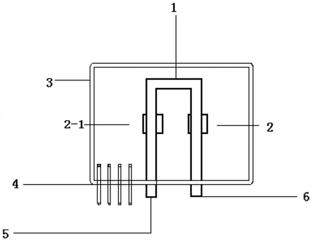
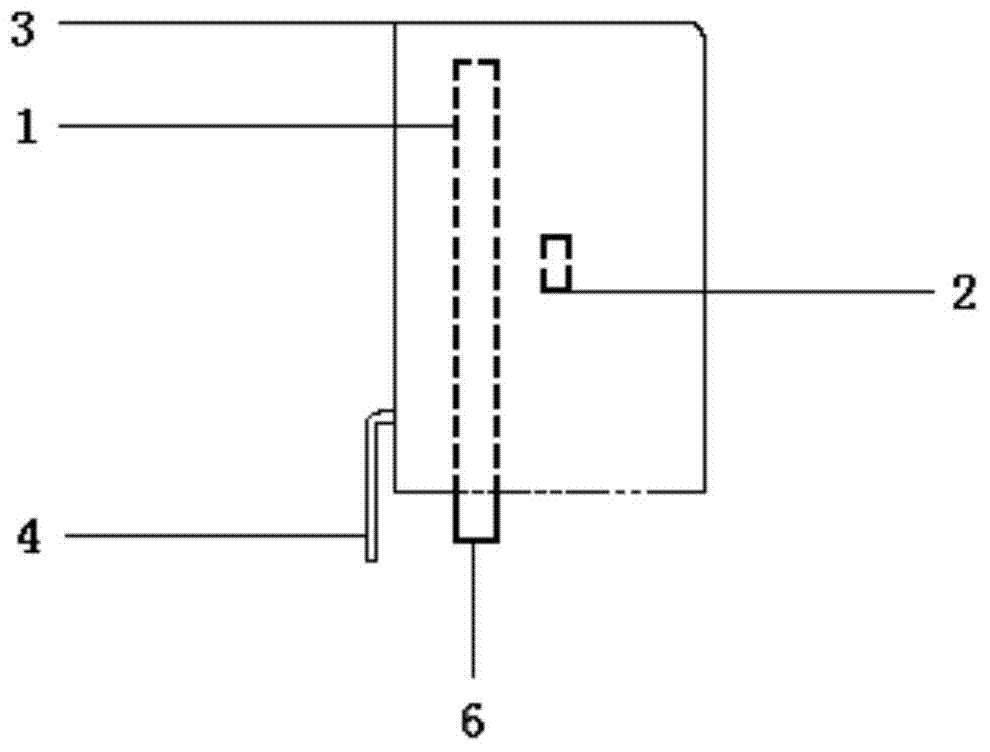
[0016] Such as figure 1 As shown, this embodiment provides a shielded open-loop magnetic flux-free tunnel magnetoresistive sensor, which includes a sensor housing and a U-shaped wire 1, tunnel magnetoresistance 2, 2-1, and silicon steel sheets arranged in the sensor housing. 3. Wherein: the two sides of the U-shaped wire 1 are the current input terminal 5 to be measured and the current output terminal 6 to be measured respectively. The tunnel magnetoresistance, namely tunnel magnetoresistance 2 and tunnel magnetoresistance 2-1 are respectively arranged directly below the two sides of the U-shaped wire 1, and the induction direction of the tunnel magnetoresistor 2, 2-1 is parallel to the tunnel magnetism Parallel magnetic fields of the resistors, the ...


PUM


Abstract

The invention discloses a shielded open loop type magnetic gathering ring-free tunneling magnetoresistive sensor which comprises a sensor shell, and a U-shaped wire, tunneling magnetoresistors and a silicon steel sheet which are arranged in the sensor shell, wherein two sides of the U-shaped wire respectively serve as a to-be-detected current input end and a to-be-detected current output end; the tunneling magnetoresistors are respectively arranged under the two sides of the U-shaped wire; a parallel magnetic field parallel to the tunneling magnetoresistors is arranged in the induction direction of each tunneling magnetoresistor; the two tunneling magnetoresistors respectively induce a magnetic field generated by current in different directions on the two sides in the U-shaped wire, and two voltage signals are output; the silicon steel sheet is embedded in the sensor shell and is used for shielding external magnetic disturbance. According to the shielded open loop type magnetic gathering ring-free tunneling magnetoresistive sensor, the influence of temperature on the current sensor output is improved, the capacity of adapting a complex working environment through a current sensor is improved, the output accuracy of the current sensor is greatly improved in a whole temperature range, and the temperature characteristics are 7 times that of a traditional identical sensor.

Description

technical field [0001] The invention relates to a magnetic sensor, in particular to a shielded open-loop tunnel magnetoresistive sensor without a magnet gathering ring. Background technique [0002] Traditional open-loop current sensors are based on the principle of the Hall effect, a phenomenon discovered by American physicist Hall in 1897 when he was studying the mechanism of metal conduction. When the current passes through the conductor perpendicular to the external magnetic field, a potential will appear between the two end faces of the conductor perpendicular to the magnetic field and the current direction. The traditional Hall open-loop current sensor generates the current flowing through the measured conductor through the magnetic gathering ring. The magnetic field is gathered in the magnetic ring with a gap, and the Hall sensing chip is placed in the gap of the magnetic gathering ring. The magnetic field in the gap passes through the Hall sensing chip vertically, an...

Claims


Application Information

Patent Timeline
IPC IPC(8): G01R19/00G01R15/20G01R19/32
Inventor 王爱斌
Owner SHANGHAI FREESOR ELECTRONICS CO LTD
Why Eureka
Try Eureka