Electronic component and circuit module

An electronic component and electrode technology, which is applied in the direction of assembling printed circuits, printed circuit components, and circuits with electrical components, can solve the problems of large application of the winding 531a, and achieve the effect of reducing the possibility of disconnection

Active Publication Date: 2018-01-23
MURATA MFG CO LTD
View PDF4 Cites 4 Cited by
  • Summary
  • Abstract
  • Description
  • Claims
  • Application Information

AI Technical Summary

Problems solved by technology

On the other hand, the resin softens during expansion, so the

Method used


Image

  • Electronic component and circuit module
  • Electronic component and circuit module
  • Electronic component and circuit module

Examples


Embodiment approach

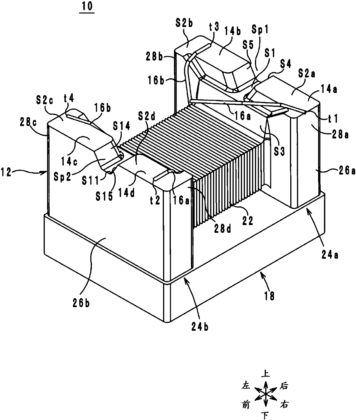
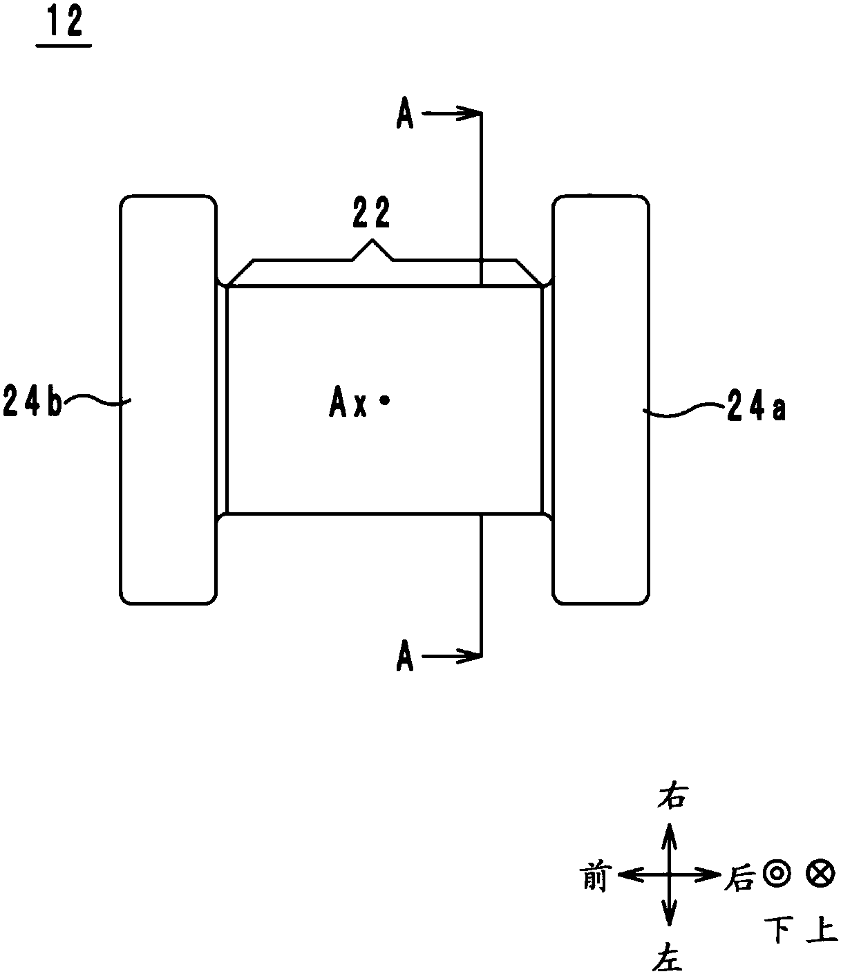
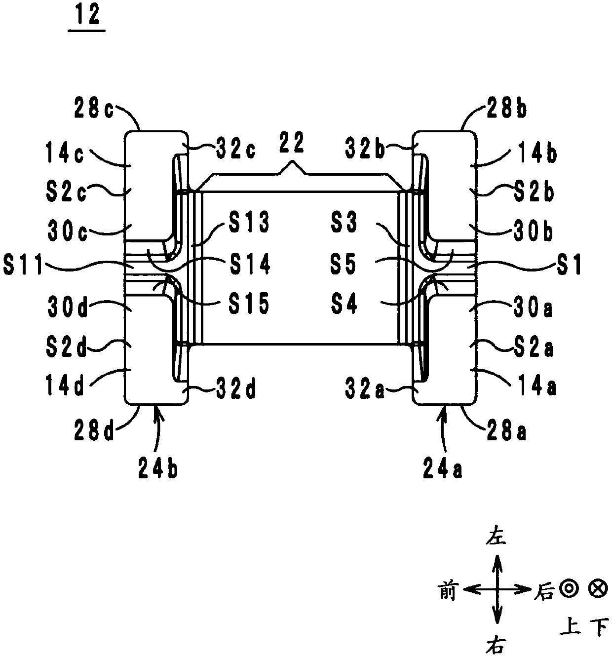
[0050] Hereinafter, an electronic component and a circuit module according to an embodiment will be described with reference to the drawings. figure 1 It is an external perspective view of the electronic component 10 . figure 2 It is a figure which looked at the iron core 12 of the electronic component 10 from the lower side. image 3 It is a figure which looked at the iron core 12 of the electronic component 10 from the upper side. Figure 4 yes figure 2 The cross-sectional structure diagram on A-A. exist Figure 4In the figure, the interval I1 from the winding core 22 to the external electrode 14a is illustrated, and the other windings 16a are omitted.

[0051] Hereinafter, the direction in which the winding core portion 22 of the core 12 of the electronic component 10 extends is defined as the front-rear direction (an example of the first direction, the rear side being an example of one side, and the front side being an example of the other side). In addition, the d...


PUM


Abstract

An electronic component and a circuit module which can reduce the possibility of line breakage during line winding are provided. The electronic component includes an iron core, a first winding, and anouter electrode. A flange of the iron core includes a body having a first surface that faces a top side and is located on the top side of a winding core of the iron core, and first and second electrode formation portions protruding toward the top side of the first surface. The outer electrode is provided on a second surface of the first electrode formation portion and is connected to the first winding. Slot space surrounded by the first and second electrode formation portions and the first surface is formed. A predetermined section between a point where the winding is separated from the winding core and a point where the winding comes into contact with the outer electrode extends toward the upper right side as viewed from the front, and does not include a portion of the first winding an entire line width of which overlaps the slot space.

Description

technical field [0001] The present invention relates to an electronic component and a circuit module including a wire-wound coil. Background technique [0002] As a conventional invention related to electronic components, for example, a wire-wound chip common mode choke coil described in Patent Document 1 is known. Figure 13 It is a perspective view of the common mode choke coil 500 described in patent document 1. exist Figure 13 In , the direction in which the winding core portion 511 extends is defined as the front-rear direction. In addition, the direction in which leg-shaped electrode portions 515a, 515b are arranged is defined as the left-right direction. In addition, a direction perpendicular to the front-back direction and the left-right direction is defined as an up-down direction. [0003] The common mode choke coil 500 includes an iron core 510, leg-shaped electrode portions 515a, 515b, and winding wires 531a, 531b. The iron core 510 includes a winding core po...

Claims


Application Information

Patent Timeline
IPC IPC(8): H01F27/24H01F27/29H01F17/00H01F17/04
CPCH01F27/24H01F27/292H01F27/2823H01F27/30H01F17/00H01F17/04H01F2017/0093H01F2017/004H05K2201/1003H05K3/284H01G4/33H01L23/13H01L23/14H01L23/32H05K1/11H05K1/181H05K3/34
Inventor 神户勇贵
Owner MURATA MFG CO LTD
Why Eureka
Try Eureka