Method for manufacturing antenna and mobile device

A technology of mobile equipment and manufacturing method, applied in the direction of antenna support/mounting device, radiating element structure, etc., capable of solving problems such as easy bending of the antenna, occupation of the internal installation space of the mobile phone, and influence of the installation of the mobile phone

Inactive Publication Date: 2018-01-23
AAC PRECISE MFG TECH CHANGZHOU
View PDF5 Cites 1 Cited by
  • Summary
  • Abstract
  • Description
  • Claims
  • Application Information

AI Technical Summary

Problems solved by technology

Since both the FPC antenna and the plastic mobile phone back case are prone to elastic deformation, and the edges of the antenna and the mobile phone back case are bonded through non-planar surfaces, the bonding accuracy between the antenna and the plastic mobile phone back case is low, and the antenna is prone to bending. In addition, the antenna and the plastic mobile phone back shell are prone to loose fit, which makes the antenna occupy more installation space inside the mobile phone and affects the installation of other components in the mobile phone.

Method used


Image

  • Method for manufacturing antenna and mobile device
  • Method for manufacturing antenna and mobile device
  • Method for manufacturing antenna and mobile device

Examples


Embodiment Construction

[0048] The present invention will be described in further detail below through specific embodiments and in conjunction with the accompanying drawings.

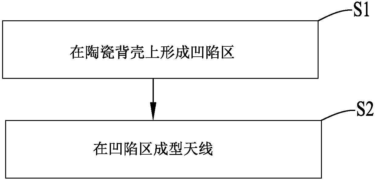
[0049] Such as figure 1 , Figure 5 , Figure 6 and Figure 7 As shown, among them, figure 1 A schematic flow chart of a method for manufacturing an antenna provided by an embodiment of the present invention, which includes the following steps:

[0050] S1, forming a recessed area 2 on the ceramic back shell 1;

[0051] The ceramic back shell 1 can specifically be a back shell made of ceramic materials in mobile devices, and the ceramic back shell 1 can be made of conventional ceramic materials, or can be made of new ceramics that meet the design requirements and have other advantages; the aforementioned The two opposing surfaces of the ceramic back shell 1 can be both flat or curved, or in other cases; the aforementioned two surfaces refer to the two opposing surfaces along the thickness direction of the ceramic back she...


PUM


Abstract

The invention relates to the field of the mobile communication technology, in particular, to a method for manufacturing an antenna and a mobile device. The provided fabrication method comprises: S1, forming a recessed region on a ceramic back shell; and S2, carrying out moulding of an antenna in the recessed region. According to the invention, the antenna manufactured by the method is not easy tobend and is in contact with a back shell of a mobile phone tightly, so that the mounting space occupied by the antenna inside mobile equipment is reduced.

Description

technical field [0001] The present invention relates to the technical field of mobile communication, in particular to an antenna manufacturing method, and also to a mobile device. Background technique [0002] With the development of science and technology, the back shell materials of mobile phones have tended to be diversified. Because ceramics have the performance of not interfering with and not weakening electromagnetic signals, it can avoid the shielding of mobile phone signals in the 5G environment and make mobile phone wireless charging technology At the same time, transparent ceramics, such as alumina ceramics, have been successfully developed, which means that mobile phone back shells made of transparent ceramic materials can also obtain higher image clarity by matching OLED screens, so in the next few years , The ceramic back shell is expected to become the standard configuration of the mobile phone back shell. [0003] Traditional antenna design schemes, such as F...

Claims


Application Information

Patent Timeline
Patent Type & Authority Applications(China)
IPC IPC(8): H01Q1/38H01Q1/24
Inventor 朱晓龙周礼义
Owner AAC PRECISE MFG TECH CHANGZHOU
Why Eureka
Try Eureka