Turnover mechanism of washing machine roller plastic piece

A washing machine drum and flip mechanism technology, which is applied in the field of the flip mechanism of the plastic parts of the washing machine drum, can solve the problems of small contact area, unfavorable manipulation, and bulky structure of the plastic parts of the washing machine drum, and achieve favorable actual control, deformation prevention, and accurate positioning Effect

Pending Publication Date: 2018-01-26
苏州市春欣塑料制品有限公司
View PDF0 Cites 0 Cited by
  • Summary
  • Abstract
  • Description
  • Claims
  • Application Information

AI Technical Summary

Problems solved by technology

[0003] However, in the process of use, it is found that the plastic parts taken out of the molding equipment are generally set vertically. If you want to place them horizontally on the assembly line, you must turn them. Most of the manipulators on the market use cylinders, Oil cylinder or hydraulic cylinder is used as power output, therefore, the structure adopted is bulky, which is not conducive to actual control
[0004] At the same time, due to the relatively large size of the plastic parts of the washing machine drum, the commonly used positioning method is to use the principle of synchronous movement of the jaws to achieve accurate positioning through a three-jaw chuck or a four-jaw chuck. However, in actual production, Few manufacturers use chuck positioning, because the cost of chuck positioning is relatively high, and the structure is relatively complicated. At the same time, the contact area with the plastic parts of the washing machine drum is too small, and the clamping force is not easy to control and other defects. , causing the positioning of the plastic parts of the washing machine drum is very inconvenient, and at the same time it is impossible to accurately complete the processing of the drum surface

Method used


Image

  • Turnover mechanism of washing machine roller plastic piece
  • Turnover mechanism of washing machine roller plastic piece
  • Turnover mechanism of washing machine roller plastic piece

Examples


Embodiment Construction

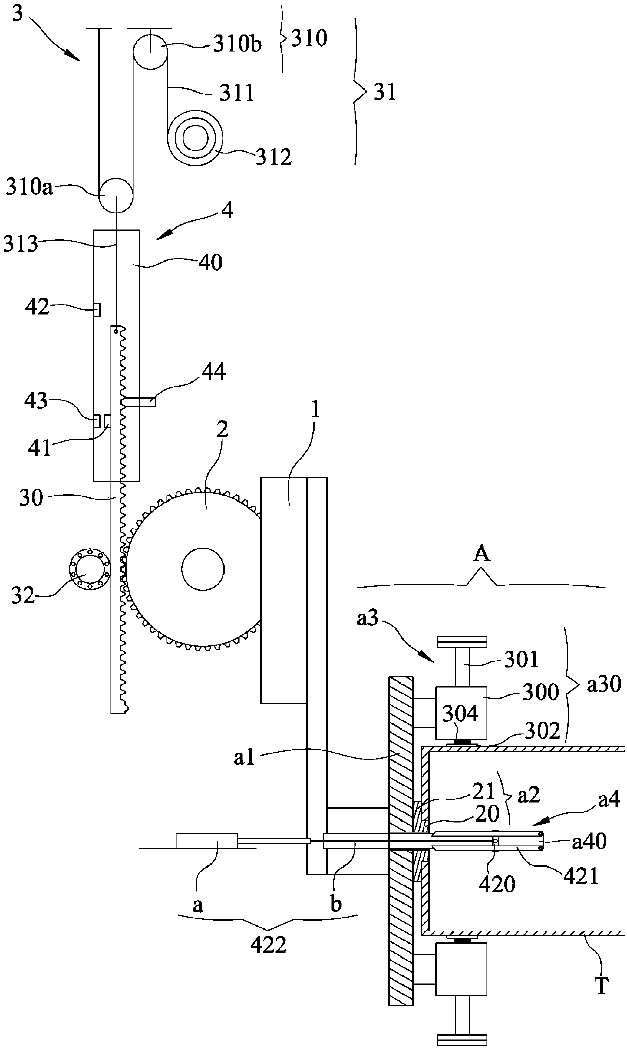
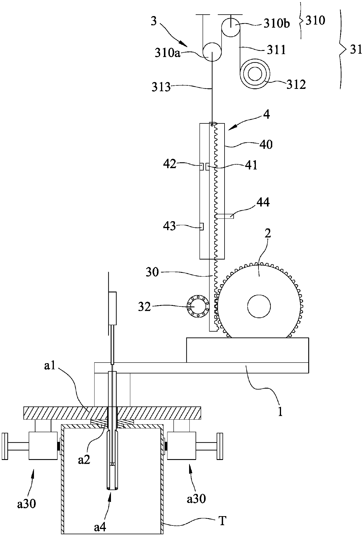
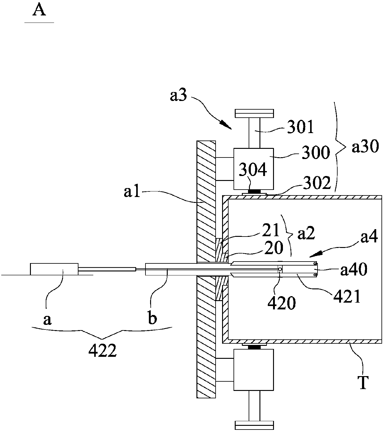
[0040] Such as Figure 1 to Figure 6 As shown, this example provides an overturning mechanism for the plastic part of the washing machine drum, which includes: a connecting frame 1, which is used to connect the positioning device A of the manipulator; Drive assembly 3, it is used to drive the rotation of gear 2, and it comprises the rack bar 30 that is positioned at the opposite side of connecting frame 1 and matches with gear 2, is used to drive the drive that rack bar 30 moves along its length direction Component 31 : the control limit assembly 4, which is used to control the movement of the rack bar 30, so that when the clip arm is in a horizontal or vertical state, the rack bar 30 stops moving.

[0041] The rack bar 30 is extended along the vertical direction. The connecting frame 1 is fixedly clamped on one side of the gear 2 .

[0042] The driving part 31 includes a pulley block 310 located at the top of the rack bar 30 , a traction rope 311 and a winding roller 312 , ...


PUM


Abstract

The invention relates to a turnover mechanism of a washing machine roller plastic piece. The turnover mechanism comprises a connecting frame, a gear, a driving assembly and a control limiting assembly; the connecting frame is connected with a positioning device of a mechanical arm, and the positioning device comprises a positioning support, a center positioning piece, an external positioning pieceand an internal supporting piece; the axis of the gear is horizontally arranged, and the connecting frame is arranged on one side of the gear; the driving assembly is used for driving the gear to rotate and comprises a rack rod located on the opposite side of the connecting frame and matched with the gear and a driving component used for driving the rack rod to move in the self length direction;and the control limiting assembly is used for controlling the rack rod to move, when a clamping arm is in the horizontal or vertical state, the rack rod stops motion. The turnover mechanism can quickly and accurately achieve conversion of the horizontal state and the vertical state of the clamping arm, the size is small, the structure is simple, actual operation is facilitated, positioning is accurate and stable, and deformation caused by too large clamping force can be prevented.

Description

technical field [0001] The invention relates to the field of plastic product molding equipment, in particular to an overturning mechanism for plastic parts of a drum of a washing machine. Background technique [0002] As we all know, after the plastic parts are molded, it is necessary to use a manipulator (also called a reclaimer) to take it out of the molding equipment and transfer it to the assembly line for further assembly or other processing. However, most of the manipulators currently used are Adsorption is carried out through the principle of negative pressure. When the plastic parts are transferred to the designated position, the adsorption is stopped, and the castings are separated from the adsorption components under their own weight and enter the assembly line. [0003] However, in the process of use, it is found that the plastic parts taken out of the molding equipment are generally set vertically. If you want to place them horizontally on the assembly line, you ...

Claims


Application Information

Patent Timeline
Patent Type & Authority Applications(China)
IPC IPC(8): B29C43/50
Inventor 陈杰
Owner 苏州市春欣塑料制品有限公司
Why Eureka
Try Eureka