Rectangular dry type shell-and-tube heat exchanger

A shell-and-tube heat exchanger, rectangular technology, applied in the direction of heat exchanger shell, indirect heat exchanger, heat exchanger type, etc., can solve the phenomenon of gas-liquid stratification intensified, the impact of heat exchange tubes, and insufficient heat exchange area To achieve the effect of weakening the gas-liquid stratification phenomenon, reducing the static pressure difference of the liquid column, and improving the heat transfer coefficient

Pending Publication Date: 2018-01-26
江苏世林博尔制冷设备有限公司
View PDF0 Cites 0 Cited by
  • Summary
  • Abstract
  • Description
  • Claims
  • Application Information

AI Technical Summary

Problems solved by technology

[0004] Tube side: circular tube box has a large height difference △h between the highest point and the lowest point of the liquid supply distribution chamber, so the static pressure difference △p of the liquid column in the chamber is relatively large, and the gas-liquid two-phase refrigerant entering the chamber ( The gaseous refrigerant has a low density and is separated upwards; the liquid refrigerant has a high density and is separated downwards) Due to the large static pressure difference △p of the liquid column in the cavity, the gas-liquid stratification phenomenon is intensified, resulting in uneven distribution of the liquid supply. The heat exchange tube distributes mostly gaseous refrigerant, the proportion of refrigerant distributed is small and the heat exchange area is large, resulting in a waste of heat exchange area; the lower heat exchange tube distributes mostly liquid refrigerant, and the proportion of refrigerant distributed is large and The heat transfer area is small, resulting in insufficient heat transfer area and incomplete evaporation of the refrigerant, which eventually leads to the suction of the compressor with liquid
[0005] S

Method used


Image

  • Rectangular dry type shell-and-tube heat exchanger
  • Rectangular dry type shell-and-tube heat exchanger
  • Rectangular dry type shell-and-tube heat exchanger

Examples


Example Embodiment

[0028] The specific embodiments of the present invention will be described in further detail below with reference to the accompanying drawings:

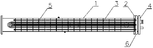
[0029] As shown in the figure, a rectangular dry shell-and-tube heat exchanger includes a broken-line shell side composed of a shell 1, a tube plate 2 and a spoiler 3, and a tube box 4 and a U-shaped heat exchange tube 5. The composition of the tube. The pipe box 4 is provided with a pipe pass inlet and an outlet, and the pipe pass inlet is located below the pipe pass outlet, which adopts a bottom in and top out manner. Shell side inlets and outlets are provided on both ends of the shell 1.

[0030] The casing 1, the tube plate 2, the tube box 3, and the spoiler 3 are all rectangular. One end of the shell 1 is closed, the tube plate 2 is installed on the other end of the shell 1, the U-shaped heat exchange tubes 5 are rectangularly arranged in the shell 1, and the U-shaped heat exchange tubes 5 pass through each spoiler 3, U-shaped The...


PUM


Abstract

The invention relates to a rectangular dry type shell-and-tube heat exchanger. The rectangular dry type shell-and-tube heat exchanger comprises a tube pass and a broken-line-shaped shell pass, whereinthe tube pass is composed of a channel and U-shaped heat exchange tubes, and the broken-line-shaped shell pass is composed of a shell, a tube sheet and spoilers; a tube pass inlet and a tube pass outlet are formed in the channel; and a shell pass inlet and a shell pass outlet are formed in the shell. The rectangular dry type shell-and-tube heat exchanger is characterized in that the shell is a rectangular shell; one end of the shell is closed; the tube sheet is arranged at the other end surface of the shell; the multiple U-shaped heat exchange tubes are arranged in the shell in a rectangularmode; the end parts of the U-shaped heat exchange tubes are supported by the tube sheet; the channel is arranged on the outer side of the tube sheet and is used for performing shunting on the U-shapedheat exchange tubes; and a rectangular sealing gasket is arranged between the channel and the tube sheet.

Description

technical field [0001] The invention belongs to the technical field of refrigeration (heat pump) air conditioners and low-temperature (freezing) units, and in particular relates to a new structure of a dry shell-and-tube heat exchanger. Background technique [0002] Dry-type evaporator, as the name implies, dry-type evaporator is a tube side where gas-liquid two-phase refrigerant enters the evaporator directly controlled by capillary tube, orifice plate, thermal expansion valve or electronic expansion valve, and the refrigerant liquid is completely transformed into gas in the tube. , while the cooled (heated) medium flows in the shell side outside the heat exchange tube. The shell side is equipped with a spoiler, which is used to change the fluid flow direction. It is often used in the design of the shell side medium flow channel in the dry evaporator, which can not only improve the heat transfer effect, but also play the role of supporting the tube bundle. Determine the nu...

Claims


Application Information

Patent Timeline
IPC IPC(8): F25B39/02F28D7/06F28F9/00F28F9/24
Inventor 唐兴吴风雷
Owner 江苏世林博尔制冷设备有限公司
Why Eureka
Try Eureka