Check patentability & draft patents in minutes with Patsnap Eureka AI!

Symbol table-based programmable logic debugging method and system

A programming logic and symbol table technology, applied in the field of programmable logic debugging, can solve the problems of only viewing, running state information cannot be dynamically generated, etc., and achieve the effect of improving the means of acquisition and analysis

Active Publication Date: 2018-01-26
NR ELECTRIC CO LTD +1
View PDF7 Cites 2 Cited by
  • Summary
  • Abstract
  • Description
  • Claims
  • Application Information

AI Technical Summary

Problems solved by technology

The traditional programmable logic of embedded devices has the following two problems: 1. When debugging, only the final logic result can be viewed; 2. Or some systems can view the intermediate running state, but each running state information is statically generated in advance. cannot be generated dynamically

Method used


Image

  • Symbol table-based programmable logic debugging method and system

Examples


Embodiment approach

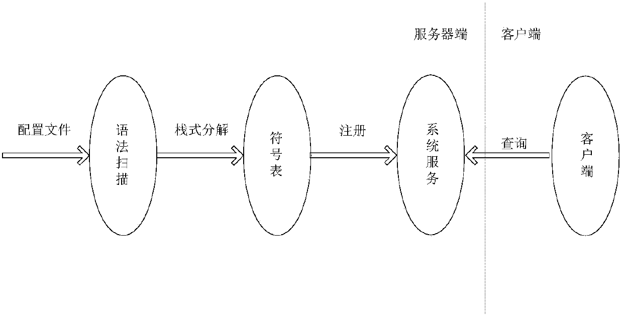
[0022] A specific method and system for debugging programmable logic based on a symbol table will be used to illustrate the specific implementation method of the present invention below. data flow see figure 1 , the specific implementation methods include:

[0023] 1. Syntax scanning:

[0024] (1) Build logic diagrams in a graphical way, with icons including four arithmetic operations, logical operations, conditional statements, jump statements, loop statements, function blocks, etc., to generate configuration files for logical function descriptions;

[0025] (2) The operating system side loads the configuration file into the shared memory, and the processor side reads the configuration information from the shared memory, checks the file CRC, and if the check is inconsistent, the device fails to start;

[0026] (3) Create summary table items, input table items, output table items, and formula table items in sequence;

[0027] 2. Symbol table:

[0028] (1) When scanning the...


PUM


Abstract

The invention discloses a symbol table-based programmable logic debugging method. The method comprises the following steps of: obtaining and analyzing a logic page built in a graphical manner by a tool so as to generate programmable logic configuration information; scanning input information by a processor and generating a logic module expressed by the input information into a corresponding data structure; generating a symbol table by the data structure step by step from outside to inside according to a symbol matching rule on the basis of a stack structure; registering a variable for a systemby the symbol table so as to generate a corresponding signal entity; and querying a corresponding system variable by a client according to the symbol table so as to obtain system operation state information. The invention furthermore discloses a system corresponding to the symbol table-based programmable logic debugging method. According to the method, a symbol encoding rule is adopted, so that the generation of a unique variable is ensured and the acquisition and analysis of the system operation state information is convenient.

Description

technical field [0001] The invention belongs to the field of embedded devices, and relates to a symbol table-based programming logic debugging method and system. Background technique [0002] In recent years, the large-scale application of embedded devices has put forward more extensive and more flexible requirements for programmable logic. The traditional programmable logic of embedded devices has the following two problems: 1. When debugging, only the final logic result can be viewed; 2. Or some systems can view the intermediate running state, but each running state information is statically generated in advance. Cannot be generated dynamically. In order to solve this problem, it is necessary to propose a new technology and new method of programmable logic debugging according to the characteristics of embedded devices and combined with engineering practice. Contents of the invention [0003] Aiming at the defects and deficiencies in the prior art, the present invention...

Claims


Application Information

Patent Timeline
IPC IPC(8): G06F8/30G06F8/34
Inventor 程立周磊陈宏君熊慕文李少卿
Owner NR ELECTRIC CO LTD
Features
  • R&D
  • Intellectual Property
  • Life Sciences
  • Materials
  • Tech Scout
  • Unparalleled Data Quality
  • Higher Quality Content
  • 60% Fewer Hallucinations
Learn More