Multi-part safety device for syringe

A technology of safety devices and syringes, which is applied in the direction of hypodermic injection devices, drug devices, and other medical devices, and can solve problems such as limiting the application range of safety devices, difficult implementation, and difficult production

A technology of safety devices and syringes, which is applied in the direction of hypodermic injection devices, drug devices, and other medical devices, and can solve problems such as limiting the application range of safety devices, difficult implementation, and difficult production

CN107635608AActive Publication Date: 2018-01-26GERRESHEIMER REGENSBURG GMBH

Image

  • Multi-part safety device for syringe
  • Multi-part safety device for syringe
  • Multi-part safety device for syringe

Examples


Embodiment Construction

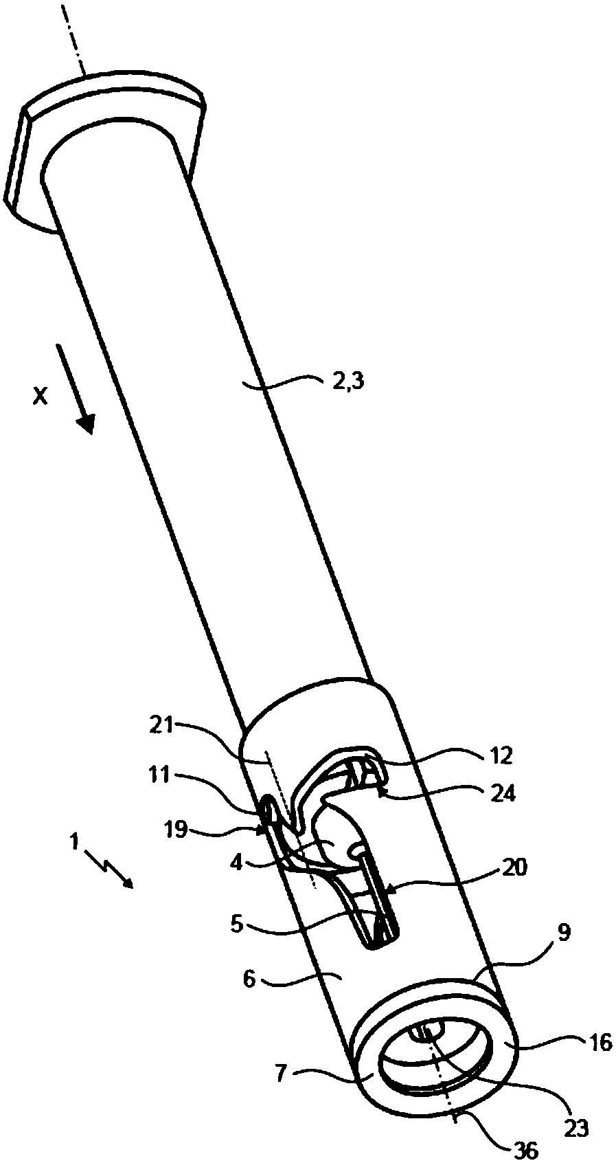
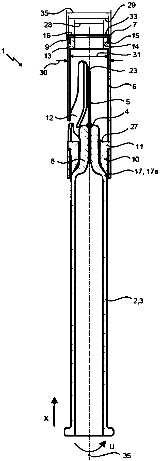
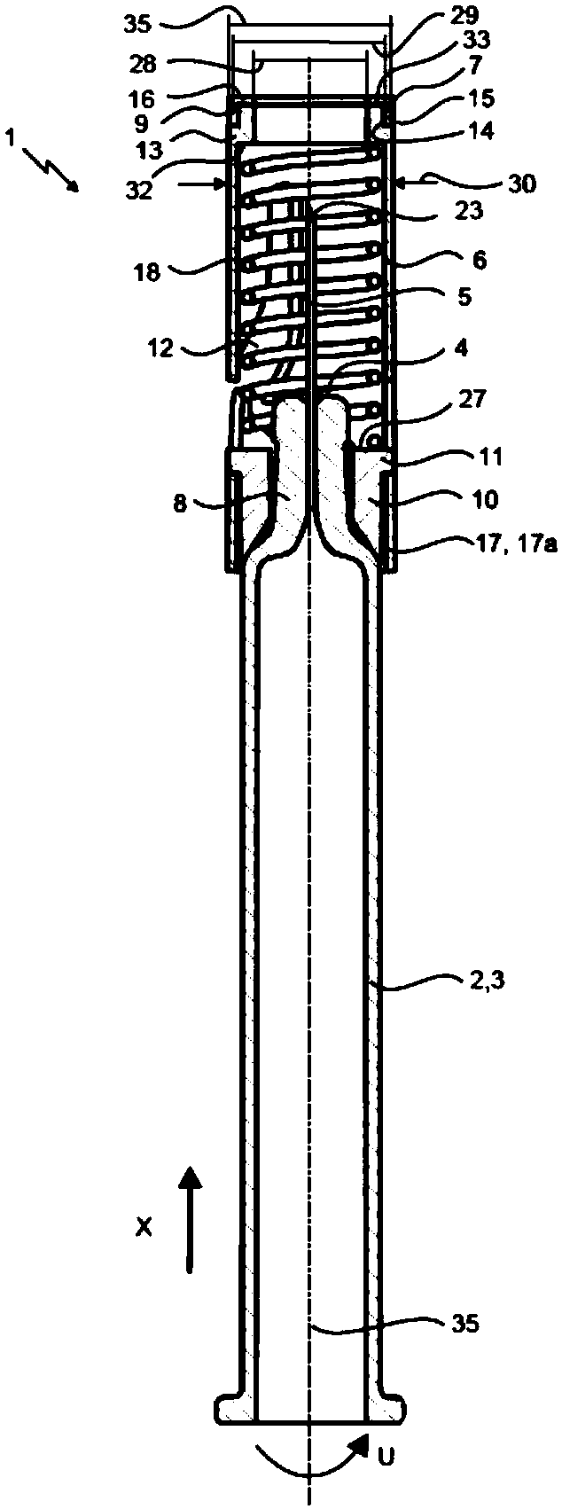
[0033] figure 1 is an isometric view of a syringe (2) including a safety device (1) for avoiding stab wounds. figure 2 and 3 Respectively, a sectional view of a syringe (2) including a safety device (1).

[0034] The syringe (2) comprises a syringe body (3) designed as a hollow cylinder. The syringe body has a distal region (8) comprising a distal end (4). A piercing device (5) is provided at the distal end (4). The piercing device 5 is connected to the cavity of the syringe body 3 via a hole in the distal region 8, so that when the syringe (2) is used, the medium to be injected can be expelled from the chamber through the piercing device 5. The distal region (8) is designed as a conical end piece with a smaller outer diameter than the syringe body (3). The syringe also has a transition region (25) in which the outer diameter of the syringe body (3) transitions into the outer diameter of the end piece.

[0035] A safety device (1) for a syringe (2) with a syringe body ...


PUM


Abstract

The invention relates to a safety device for a syringe for avoiding stab wounds, said syringe having a syringe body and a piercing means arranged on the distal end of the syringe body. The safety device comprises a sleeve element (6) that extends along an axial direction (X) and encloses at least partly the piercing means and the syringe body, said sleeve element being rotatably mounted on a distal end region of the syringe body. The safety device is characterized by comprising a contact element (7) which contacts the skin of a patient when the syringe is used, said contact element being arranged on the distal end of the sleeve element and being rotatable independent of the sleeve element.

Description

technical field [0001] The present invention relates to a safety device for avoiding stab wounds for a syringe having a syringe body and a piercing device at the distal end of the syringe body, the safety device comprising an axially (X) extending and at least partially surrounding A piercing device and a sleeve element of the syringe body, the sleeve element being rotatably arranged on the distal end region of the syringe body. Background technique [0002] Universal safety devices for avoiding stab wounds are known in the prior art. The use of such a safety device is particularly applicable in the case of prefilled syringes. The syringe is very simple to handle because the medium does not have to be transferred into the syringe before use. Also, even in an emergency, the chances of using the wrong medication are very low. For vaccines and countless other pharmaceuticals, they are currently the primary packaging material of choice. These syringes are usually manufacture...

Claims


Application Information

Patent Timeline
26 Jan 2018
Publication
CN107635608A
IPC
A61M5/32
CPC
A61M5/326; A61M5/3272; A61M2005/3267; A61M2205/02; A61M5/3221; A61M5/3271
Inventors
安德烈亚斯·弗腊斯; 马克西米兰·沃格尔