Microphone assembly with a replaceable part

a technology of replacing parts and microphones, applied in the direction of transducer types, coupling device connections, electrical apparatus, etc., can solve the problem of useless assembly, and achieve the effect of convenient breakage/removal and facilitate electrical conta

Active Publication Date: 2012-01-24
SONION NEDERLAND
View PDF10 Cites 89 Cited by
  • Summary
  • Abstract
  • Description
  • Claims
  • Application Information

AI Technical Summary

Benefits of technology

[0012]In the present invention, an easily breakable / removable electrical connection is a connection which is broken without breaking the base element or the removable element, and in particular without breaking or destroying the first and second surface parts.
[0019]It is preferable that the zebra-type rubber connector with anisotropic conductivity is elastically compressible and can be installed by area-contacting it with, for example, the surface parts of the base element and the removable element. When the rubber connector is elastically compressible, it can elastically deform in an appropriate manner to be compressed between the base element and the removable element. Thus, the rubber connector can establish secure a real contact between the two sets of surfaces. As a result, this increases the reliability of the electric connection.
[0023]In addition, it is preferred, when the connection between the first and second surface parts is solderless and resilient, that the removable element and base element are positioned so that the removable part, when attached to the housing, biases the removable element toward the resilient means and the base element. In this manner, removal of the removable part will facilitate easy removal of the removable element, and the providing of the biasing force is automatically provided when re-engaging the housing and the removable part.

Problems solved by technology

This, however, brings about the problem that malfunction of one of the microphone component and the chip(s) incorporating the added functionality will make the assembly useless.

Method used


Image

  • Microphone assembly with a replaceable part
  • Microphone assembly with a replaceable part
  • Microphone assembly with a replaceable part

Examples


Embodiment Construction

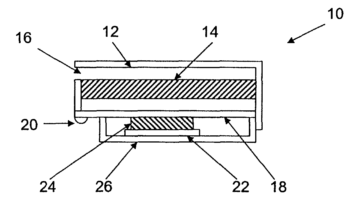
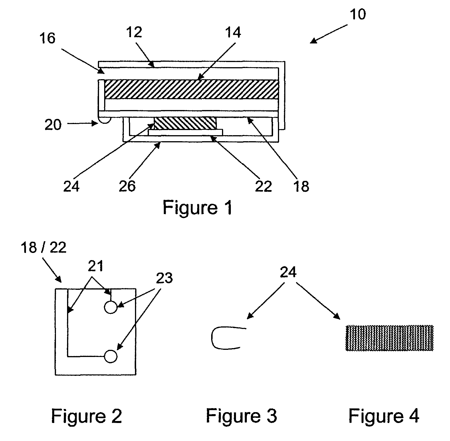
[0038]In FIG. 1, a microphone assembly 10 has a housing 12 in which a microphone element 14, such as an electret microphone element, is positioned to receive sound entering the housing 12 via a sound inlet 16. A base element 18 (also shown in FIG. 2) is positioned inside, and is fixed to, the housing 12. As may be seen from FIG. 2, the base element 18 comprises therein or thereon conductors 21 and conducting surfaces 23 through which the conductors 21 may be connected to external elements as will be clear from the below description.

[0039]One or more of the conductors 21 is / are electrically connected to solder bumps 20 positioned on the base element 18 on the outer side of the housing 12 in order to obtain electrical connection from outside the housing 12 to the surfaces 23 of the base element 18. Alternatively, the base element 18 may be comprised fully within the housing, and connecting means are provided through the housing walls to solder bumps 20 provided outside the housing. Th...


PUM


Abstract

The invention relates to a microphone assembly comprising a housing, a microphone element within the housing, a base element, contacting elements, a removable element, and connecting means. The housing is configured such that it may be opened and re-closed. The base element is positioned inside the housing and comprises one or more first electrical conductors. The base element comprises one or more first conducting surface parts connected to one or more of the first conductors. The contacting elements facilitate electrical contact between one or more of the first conductors and one or more conductors positioned outside the housing. The removable element is positioned within the housing and comprises one or more second electrically conductive surface parts. The connecting means provides an easily breakable / removable electrical connection between a first surface part and a second surface part.

Description

CROSS-REFERENCE TO RELATED APPLICATION[0001]This application claims the benefit of U.S. Provisional Application Ser. No. 60 / 997,114, filed on Oct. 1, 2007, which is hereby incorporated by reference in its entirety.FIELD OF THE INVENTION[0002]The present invention relates to a microphone assembly with a replaceable or removable part positioned inside the housing.BACKGROUND OF THE INVENTION[0003]Today, it is more and more common to combine standard microphones, such as for use in hearing aids, in-ear monitors and the like, with additional functionality, such as amplifiers, sensors, DSP's or the like. This, however, brings about the problem that malfunction of one of the microphone component and the chip(s) incorporating the added functionality will make the assembly useless. The present invention aims at solving this problem.[0004]Prior art systems of this overall type may be seen, for example, in WO00 / 74437, EP0888031, and U.S. Pat. No. 6,366,678.SUMMARY OF THE INVENTION[0005]In a fi...

Claims


Application Information

Patent Timeline
Patent Type & Authority Patents(United States)
IPC IPC(8): H04R25/00
CPCH01R13/2414H04R19/016H04R1/02H04R25/604
Inventor VAN HALTEREN, AART ZEGERVAN HAL, PAUL CHRISTIAAN
Owner SONION NEDERLAND
Why Eureka
Try Eureka