Member of connecting electrode in battery module

a battery module and electrode terminal technology, applied in the direction of cell components, sustainable manufacturing/processing, flat cell grouping, etc., can solve the problems of electrical connection between the electrode terminals necessary for constructing the battery module, subject to a large number of external impacts and vibrations, and low manufacturing costs of pouch-shaped batteries. , to achieve the effect of limited installation spa

Active Publication Date: 2011-07-12
LG ENERGY SOLUTION LTD
View PDF19 Cites 26 Cited by
  • Summary
  • Abstract
  • Description
  • Claims
  • Application Information

AI Technical Summary

Benefits of technology

[0014]Specifically, it is an object of the present invention to provide an electrode terminal connecting member that is capable of easily accomplishing the electrical connection and mechanical coupling between a plurality of cell modules of a middle- or large-sized battery module, thereby improving the productivity and safety of the middle- or large-sized battery module.
[0041]The middle- or large-sized battery module and the battery module assembly according to the present invention are preferably used as a power source for electric vehicles and hybrid electric vehicles, which have a limited installation space and are exposed to frequent vibrations and strong impacts, in consideration of the installation efficiency and the structural stability.

Problems solved by technology

Furthermore, devices, which are subject to a large number of external impacts and vibrations, such as electric bicycles and electric vehicles, require stable electrical connection and physical coupling between components constituting the battery module.
Especially, much interest is currently generated in the pouch-shaped battery, including a sheathing member made of an aluminum laminate sheet, because the weight of the pouch-shaped battery is small, and the manufacturing costs of the pouch-shaped battery are low.
First, the pouch-shaped battery is constructed in a structure in which the plate-shaped electrode terminals protrude from the upper end of the battery case, with the result that the electrical connection between the electrode terminals necessary for constructing a battery module is difficult. The electrical connection between the electrode terminals is accomplished generally by coupling the electrode terminals to each other by welding using wires, plates, or bus bars; however, the coupling between the plate-shaped electrode terminals by welding is not easy. Generally, the plate-shaped electrode terminals are partially bent, and the plates or the bus bars are welded to the bent portions of the plate-shaped electrode terminals, which requires skilled technique and complicates a process for electrically connecting the electrode terminals to each other. Furthermore, the coupled region may be separated from each other due to external impact, which causes the defect of the pouch-shaped battery.
Secondly, the pouch-shaped battery has a low mechanical strength. For this reason, additional members for maintaining stable coupling and assembly are required when a plurality of batteries are stacked to manufacture a battery module. For example, additional mounting members, such as cartridges, in each of which one or more unit batteries mounted, are used when the pouch-shaped batteries are stacked to manufacture the battery module. The cartridges are stacked to manufacture the battery module.
Furthermore, a space necessary to couple, weld, or solder the members for the mechanical coupling and electrical connection is required, with the result that the total size of the system is increased.
In addition, when the pouch-shaped battery is applied to a device, such as a vehicle, to which external forces, such as vibrations and impacts, are continuously applied, the output of the device may be unsafe and a short circuit may occur due to the increase of the contact resistance at the electrical connection region of the pouch-shaped battery.

Method used


Image

  • Member of connecting electrode in battery module
  • Member of connecting electrode in battery module
  • Member of connecting electrode in battery module

Examples


Embodiment Construction

[0056]Now, preferred embodiments of the present invention will be described in detail with reference to the accompanying drawings. It should be noted, however, that the scope of the present invention is not limited by the illustrated embodiments.

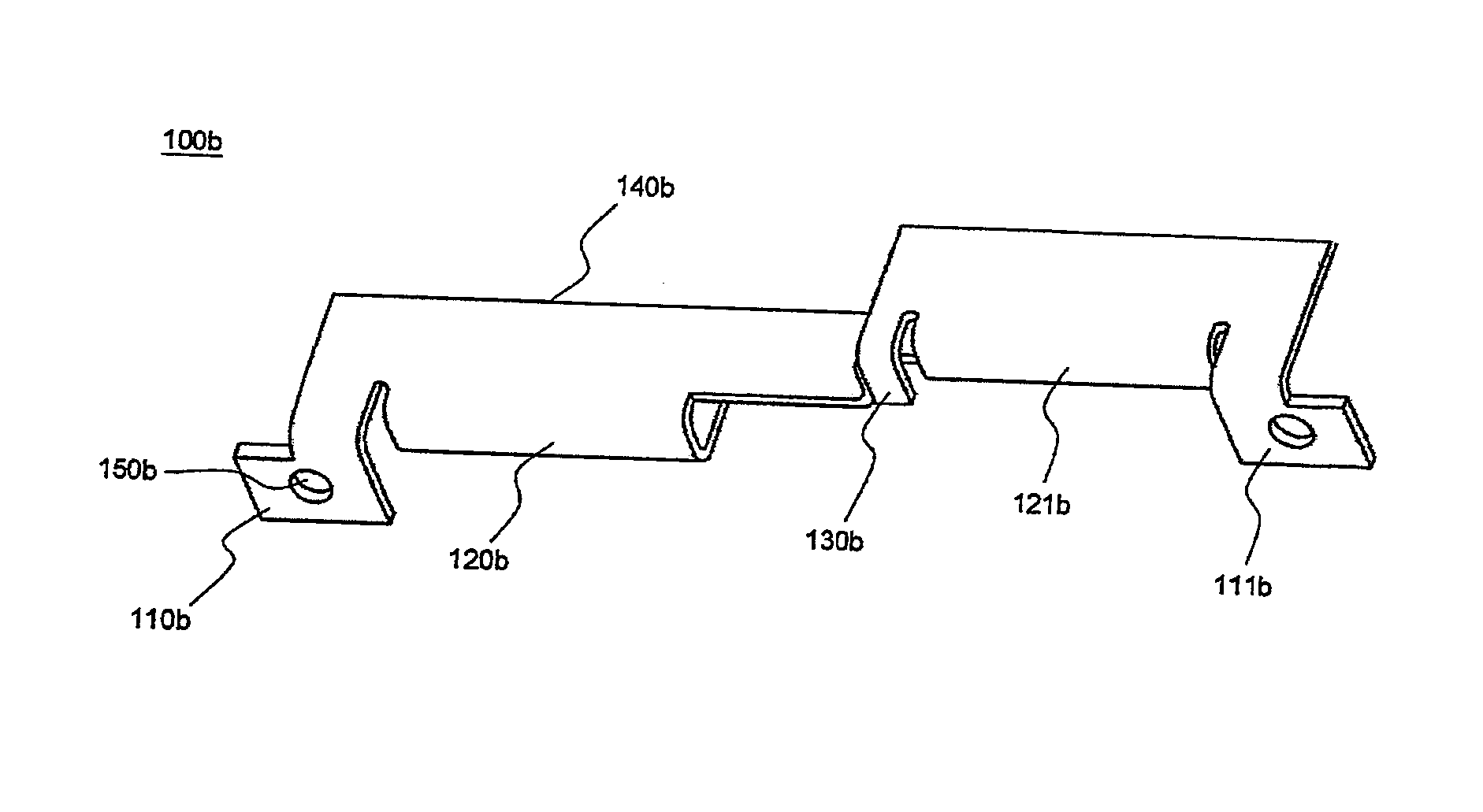
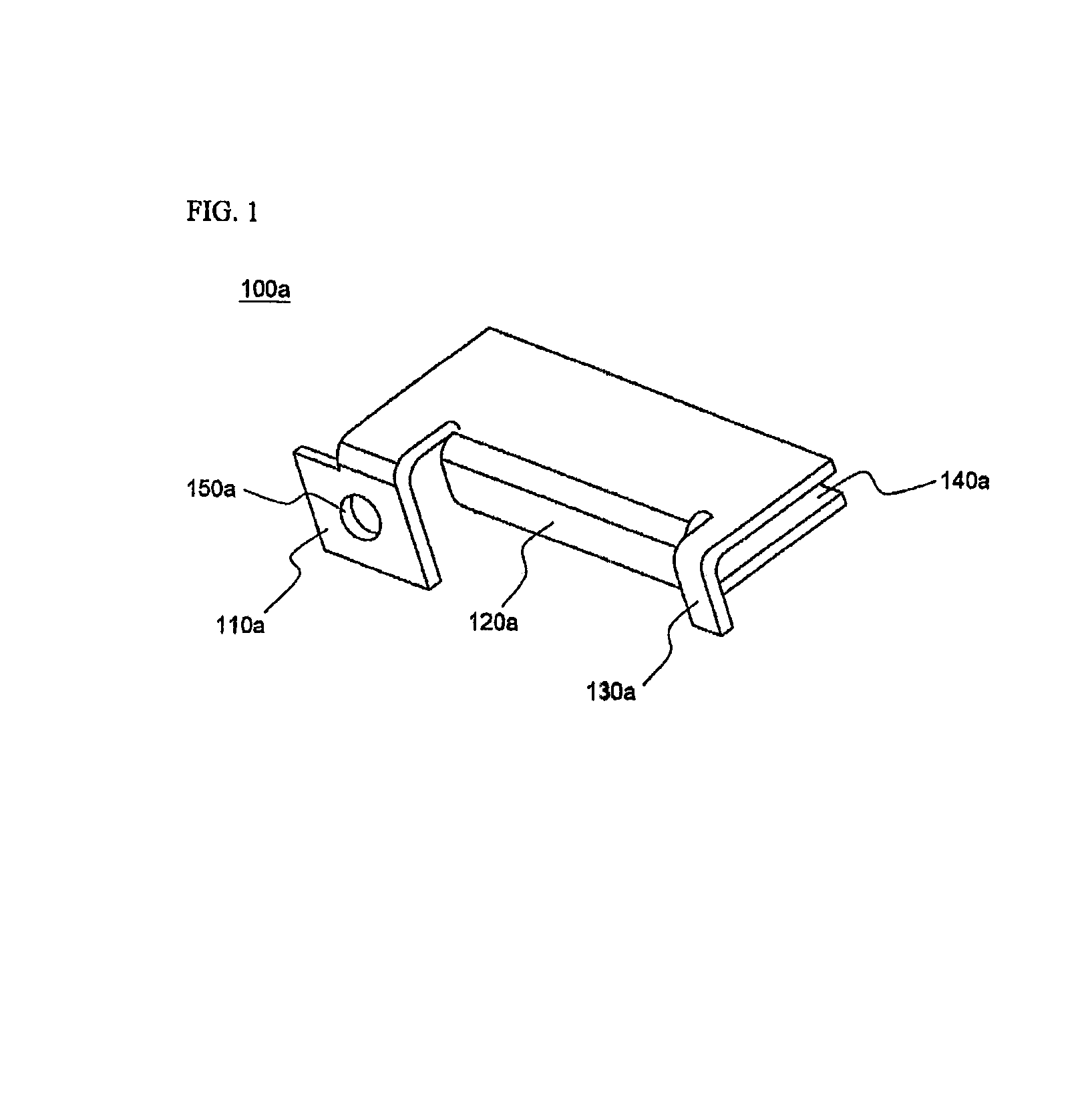
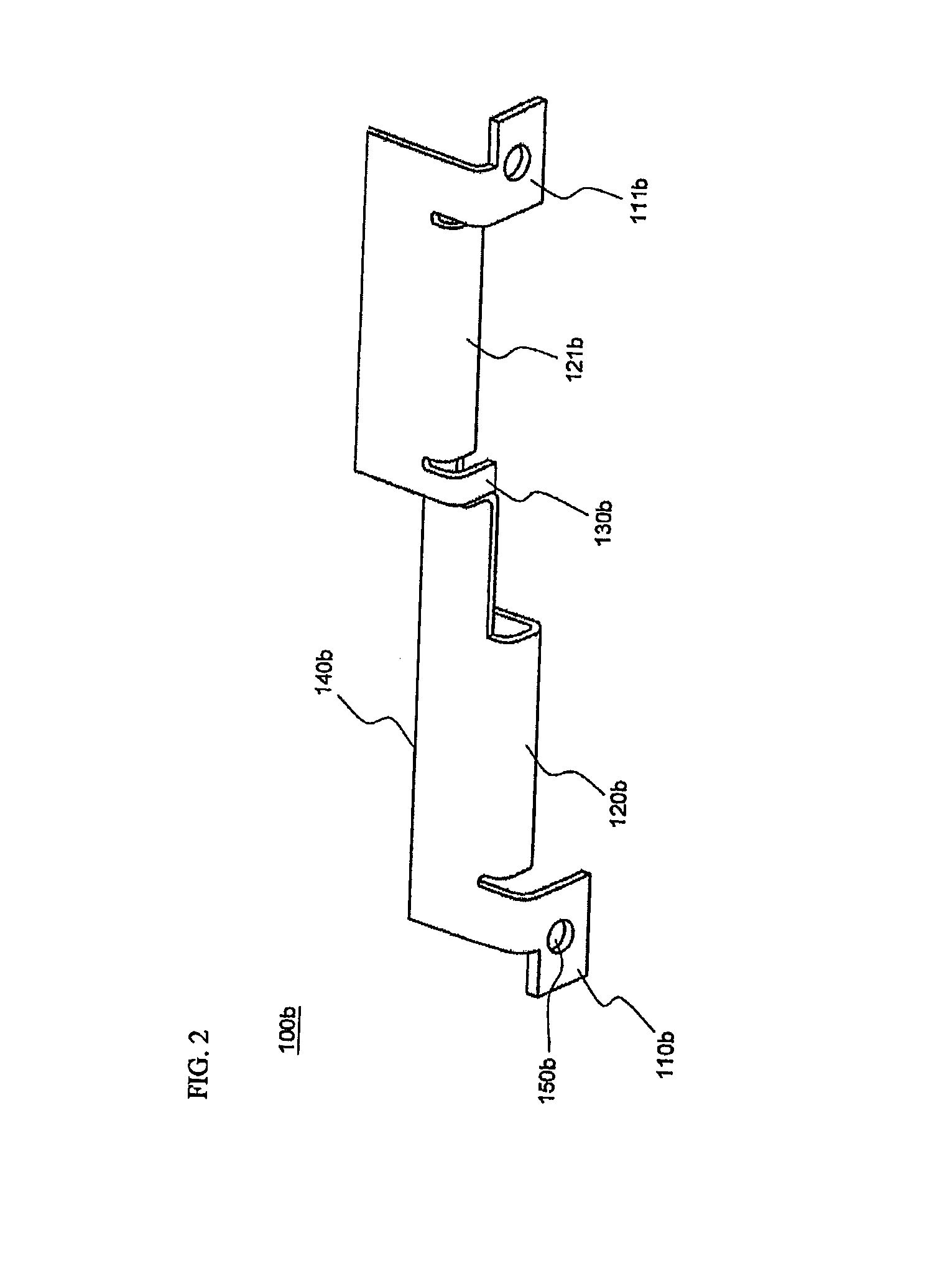
[0057]FIGS. 1 to 3 are typical views illustrating various electrode terminal connecting members according to preferred embodiments of the present invention, and FIG. 4 is a typical view illustrating a mounting insulation member, to which the electrode terminal connecting members are mounted during the construction of a battery module.

[0058]For easy understanding, the electrode terminal connecting member 100a shown in FIG. 1 is referred to as an “A-type connecting member,” the electrode terminal connecting member 100b shown in FIG. 2 is referred to as a “B-type connecting member,” and the electrode terminal connecting member 100c shown in FIG. 3 is referred to as an “C-type connecting member.”

[0059]Referring to these drawings, the electrode t...


PUM

PropertyMeasurementUnit
heightsaaaaaaaaaa
thicknessaaaaaaaaaa
sizeaaaaaaaaaa

Abstract

Disclosed herein is an electrode terminal connecting member for electrically interconnecting plate-shaped secondary battery cells (‘battery cells’) constituting a battery module, wherein the electrode terminal connecting member includes a coupling part (‘bent coupling part’) bent to form a groove at the rear of the electrode terminal connecting member such that a plate-shaped electrode terminal (‘battery cell electrode terminal’) of each battery cell is inserted into the groove, an external input and output terminal protruding toward the front of the electrode terminal connecting member while being bent, and a voltage detection terminal protruding toward the front of the electrode terminal connecting member while being bent.

Description

FIELD OF THE INVENTION[0001]The present invention relates to an electrode terminal connecting member, and, more particularly, to an electrode terminal connecting member for electrically interconnecting plate-shaped secondary battery cells (‘battery cells’) constituting a battery module, wherein the electrode terminal connecting member includes a coupling part (‘bent coupling part’) bent to form a groove at the rear of the electrode terminal connecting member such that a plate-shaped electrode terminal (‘battery cell electrode terminal’) of each battery cell is inserted into the groove, an external input and output terminal protruding toward the front of the electrode terminal connecting member while being bent, and a voltage detection terminal protruding toward the front of the electrode terminal connecting member while being bent.BACKGROUND OF THE INVENTION[0002]Recently, a secondary battery, which can be charged and discharged, has been widely used as an energy source for wireless...

Claims


Application Information

Patent Timeline
Patent Type & Authority Patents(United States)
IPC IPC(8): H01M6/42H01M6/46H01M2/24H01M6/12H01M50/211H01M50/296H01M50/503H01M50/528H01M50/529H01M50/569
CPCH01M2/206H01M2/1077Y02E60/10Y02P70/50H01M50/296H01M50/569H01M50/503H01M50/211H01M50/50H01M50/502H01M50/528H01M10/613H01M10/643H01M10/6566
Inventor SHIN, YONGSHIKKIM, JEEHOHA, JIN WOONG
Owner LG ENERGY SOLUTION LTD
Why Eureka
Try Eureka