Guide rail conveying device and use method thereof

A technology for handling devices and guide rails, which is applied in transportation and packaging, ship parts, ships, etc. It can solve the problems of difficult handling and positioning of guide rails, and achieve the effects of convenient transportation and installation, enhanced stability, and simplified procedures

Active Publication Date: 2018-12-07
SHANGHAI JIANGNAN CHANGXING SHIPBUILDING
View PDF13 Cites 1 Cited by
  • Summary
  • Abstract
  • Description
  • Claims
  • Application Information

AI Technical Summary

Problems solved by technology

[0003] In view of the deficiencies in the prior art, the object of the present invention is to provide a guide rail handling device and its use

Method used


Image

  • Guide rail conveying device and use method thereof
  • Guide rail conveying device and use method thereof
  • Guide rail conveying device and use method thereof

Examples


Embodiment 1

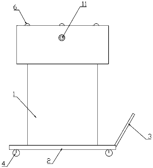
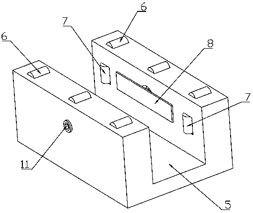
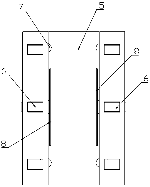
[0047] Embodiment 1: as Figure 1 to Figure 6 As shown, a kind of guide rail handling device comprises a trolley, a lifting mechanism 1 and a top carrying mechanism, and the trolley comprises a base plate 2 and a handle 3, and the handle 3 is arranged on one side of the base plate 2, and the lower surface of the base plate 2 is The four corners of each are provided with a caster 4 with brakes, the lifting mechanism 1 is arranged on the upper surface of the base plate 2, and the top carrying mechanism is arranged on the top of the lifting mechanism 1, and the top carrying mechanism includes a bearing groove 5 and Two locking mechanisms, the tops of the two side walls of the bearing groove 5 are provided with more than two horizontal rollers 6, the central axes of the horizontal rollers 6 are perpendicular to the bearing groove 5, and the bearing groove 5 has two The inner sides of the side walls are provided with more than two vertical rollers 7, and a horizontal threaded hole ...

Embodiment 2

[0073] Embodiment 2: As a kind of improved scheme of embodiment 1, such as Figure 7 As shown, as a further preference, the handling device further includes an upper cover 14 , the upper cover 14 covers the top carrying mechanism, and the upper cover 14 and the top carrying mechanism are connected by a lock 15 mechanism.

[0074] The handling device also includes an upper cover 14, which improves the flatness of the upper end of the top bearing mechanism and facilitates the operator to work on the upper cover 14, thereby increasing the function of the device.

[0075] Preferably, there are four locking buckles 15, and the four locking buckles 15 are respectively arranged at the four corners of the top carrying mechanism.

[0076] The upper cover 14 and the top carrying mechanism are connected by four locks 15, thereby enhancing the stability of the connection between the top carrying mechanism and the upper cover 14, and improving the safety of the operator standing on the upp...


PUM


Abstract

The invention discloses a guide rail conveying device and a use method thereof, and belongs to the technical field of ship construction. The guide rail conveying device comprises a plate trailer, a lifting mechanism and a top carrying mechanism; the plate trailer comprises a bottom plate and a handle; casters are arranged at the lower surface of the bottom plate; the lifting mechanism is arrangedon the upper surface of the bottom plate; the top carrying mechanism is arranged at the top of the lifting mechanism and comprises a bearing groove and two locking mechanisms; horizontal rollers are arranged at the tops of the two side walls of the bearing groove; vertical rollers are arranged on the inner sides of the two side walls of the bearing groove; one horizontal threaded hole is formed ineach of the two side walls of the bearing groove; the two locking mechanisms are arranged on the two sides of the bearing groove symmetrically and comprise locking plates and threaded rods; the two threaded rods penetrate through the two horizontal threaded holes; and the head ends of the threaded rods are connected with the locking plates through bearings. The guide rail conveying device is usedfor carrying guide rails and can jack the guide rails to the lower surface of a shifting board, manpower and material resources consumed by carrying the guide rails are saved, and the construct efficiency of ship is improved.

Description

technical field [0001] The invention belongs to the technical field of ship building, and in particular relates to a guide rail handling device and an application method thereof. Background technique [0002] When the 13500TEU guide rail platform assembly is pre-assembled, the transverse compartment adopts the method of not turning over, which requires the operator to insert the guide rails one by one on the opposite side of the transverse compartment in advance. After arriving at the approximate position, one end is placed on the round tube, and the other end is hoisted and slowly rolled to the required position. Then the staff hangs the lifting hoist on the compartment member and lifts it for installation. Safety and manpower are quite big problems, and hoisting hoists will also cause deformation of certain segmental ribs; and the use of cranes in today's high-speed hoisting work in docks has caused time wastage. Contents of the invention [0003] In view of the defici...

Claims


Application Information

Patent Timeline
IPC IPC(8): B65G35/00B63B9/00
CPCB63B71/00B65G35/00B65G2201/0214
Inventor 王佳程崔玉肖聪于勤超黄春宏曹明
Owner SHANGHAI JIANGNAN CHANGXING SHIPBUILDING
Why Eureka
Try Eureka