
Sorting and coding conveyor for stainless steel plates

A stainless steel plate and conveyor technology, applied in packaging and other directions, can solve the problems of stainless steel plate cutting the hands of workers, poor packing quality, and low efficiency, and achieve the effect of ensuring the quality of packing and improving work efficiency and safety

Active Publication Date: 2019-11-22
南京皓政科技有限公司
View PDF7 Cites 1 Cited by
  • Summary
  • Abstract
  • Description
  • Claims
  • Application Information

AI Technical Summary

Problems solved by technology

[0002] After the stainless steel plate is processed, in order to facilitate transportation, it generally needs to be sorted and packaged. The existing stainless steel plate products are mostly packaged manually, and during the packaging process, stainless steel plate products of different sizes and specifications are processed Manual coding and manual sorting and packaging are not only inefficient, but also often occur when the stainless steel plate cuts the hands of the staff during the packaging process of the stainless steel plate, which has certain potential safety hazards. At the same time, it is difficult to ensure the packaging by manual packing The stainless steel plates have the same shape and specification, and the packaging quality is poor. In view of the above problems, the company organized technical personnel to develop an automatic equipment for packaging and coding of stainless steel plates.

Method used


Image

  • Sorting and coding conveyor for stainless steel plates
  • Sorting and coding conveyor for stainless steel plates
  • Sorting and coding conveyor for stainless steel plates

Examples


Embodiment 1

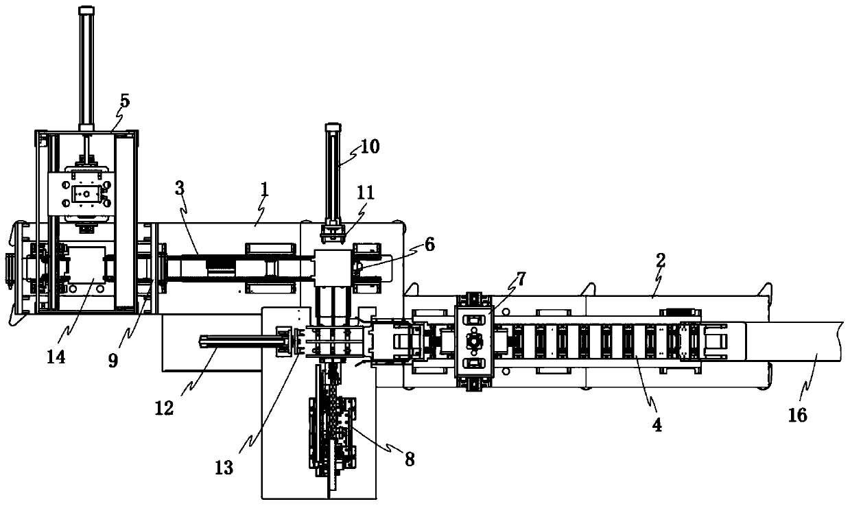
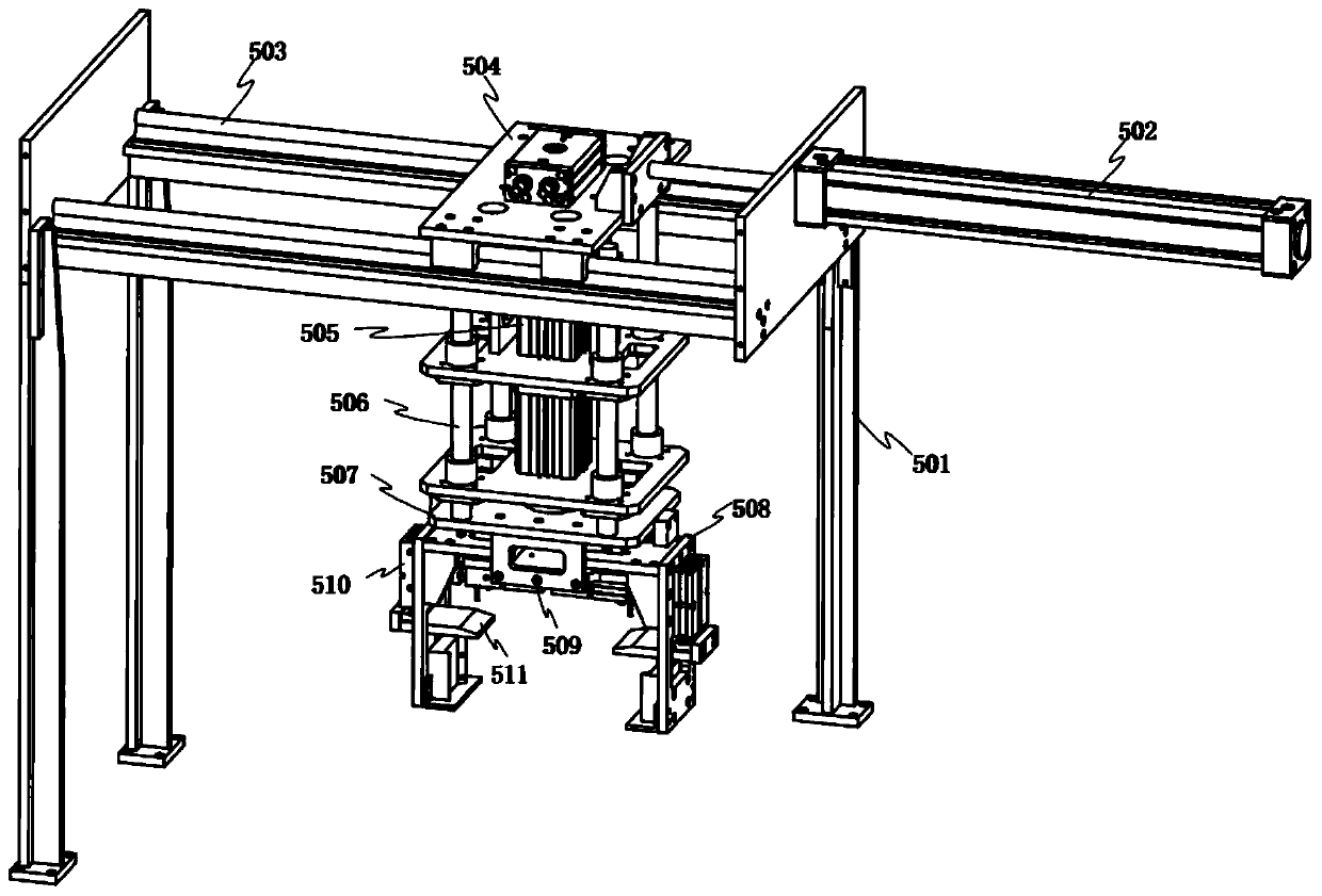
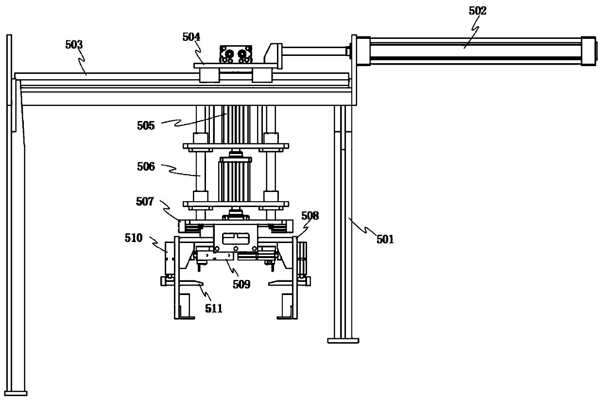
[0033] When the conveyor is in use, the horizontal drive cylinder 502 of the clamping input mechanism 5 first drives the installation slide I504 to move along the parallel slide rail I503 to the top of the stack of stainless steel plates to be sorted and coded, and then starts the lifting drive cylinder I505. The driving cylinder I505 drives the clamping plate frame 508 to move down along the vertical guide rod 506, and then starts the horizontal telescopic cylinder 509 and the vertical telescopic cylinder 510 on the clamping plate frame 508, thereby driving the clamping plate 511 to stack the stainless steel plates Clamping, then driven by the horizontal drive cylinder 502 and lifting drive cylinder I 505 to drive the clamping plate frame 508 and the clamped stainless steel plate stack to the lifting plate frame 902 of the rotary turning mechanism 9, and then driven by the horizontal telescopic cylinder 509 The clamping plate frame 508 releases the stack of stainless steel pla...

Embodiment 2

[0035] When the first conveyor belt 3 transfers the stack of stainless steel plates to the position of the jacking mechanism 6, the lifting drive cylinder III601 of the jacking mechanism 6 is activated, and the lifting drive cylinder III601 drives the movable jacking bracket 603 to lift the first conveyor belt 3 The stainless steel plate stack is lifted up, and then the ejection block I11 is driven by the push-out cylinder 10 to move the stainless steel plate stack along the surface of the movable jacking bracket 603 to the lower part of the coding mechanism 8, and then the driving motor 805 of the coding mechanism 8 is detoured Through the belt drive, the recovery runner 806 and the guide pulley 807 are driven to rotate, so that the identification code tape 809 on the rotating hanging plate 808 is rotated and output loaded with the identification code tape body, and the identification code tape body is along the guide pulley 807 and the entrainment plate 813 runs, and starts t...

Embodiment 3

[0037] Start the side clamping cylinder 702 and the positive clamping cylinder 708 of the finishing mechanism 7, and the side clamping plate 703 is driven by the side clamping cylinder 702 to clamp the end faces on both sides of the stainless steel plate, and the positive clamping cylinder 708 drives the front side through the hinged rod frame 709 The clamping plate 710 clamps the front and rear end surfaces of the stack of stainless steel plates, and then starts the pressing cylinder 707 and the straightening driving cylinder 704 of the finishing mechanism 7, and the pressing cylinder 707 drives the top finishing groove block 711 to move down, and the top finishing groove block The notch part of 711 is matched with the raised part of the end surface of the stainless steel plate stack, and the straightening drive cylinder 704 drives the side finishing rod frame 706 through the linkage rod 705 to clamp both sides of the stainless steel plate stack, and the stainless steel plate s...


PUM


Abstract

The invention relates to a sorting and coding conveyor for stainless steel plates. A first desk body and a second desk body are included, wherein the end portions of the first desk body and the seconddesk body are connected; a first conveying belt is arranged on the first desk body; the first desk body is provided with a rotating face overturning mechanism of the stainless steel plates at the convey-in end of the first conveying belt, and a clamping and convey-in mechanism for the stainless steel plates is fixed to the upper portion of the convey-in end of the first conveying belt; the firstdesk body is provided with a jacking mechanism at the convey-out end of the first conveying belt, and the position, on one side of the jacking mechanism, of the first desk body is provided with a coding mechanism; a second conveying belt is arranged on the second desk body; and a sorting mechanism for the stainless steel plates is erected at the position, on the upper portion of the second conveying belt, of the second desk body. The sorting and coding conveyor for the stainless steel plates replaces a past manual sorting and packaging manner for stainless steel plate finished products, and amanual coding manner for the finished products, automatic packaging and sorting, and surface coding of the stainless steel plate finished products are achieved, finally the finished products are conveyed out, the work efficiency and the safety of sorting and packaging are improved, and the quality of sorting and packaging is guaranteed.

Description

technical field [0001] The invention relates to the technical field of sorting and packaging equipment for stainless steel plates, in particular to a sorting and coding conveyor for stainless steel plates. Background technique [0002] After the stainless steel plate is processed, in order to facilitate transportation, it generally needs to be sorted and packaged. The existing stainless steel plate products are mostly packaged manually, and during the packaging process, stainless steel plate products of different sizes and specifications are processed Manual coding and manual sorting and packaging are not only inefficient, but also often occur when the stainless steel plate cuts the hands of the staff during the packaging process of the stainless steel plate, which has certain potential safety hazards. At the same time, it is difficult to ensure the packaging by manual packing The stainless steel plates have the same shape and specification, and the packaging quality is poor...

Claims


Application Information

Patent Timeline
IPC IPC(8): B65B35/44B65B35/58B65B63/00
CPCB65B35/44B65B35/58B65B63/005
Inventor 王毅军
Owner 南京皓政科技有限公司
Learn More