Battery module of novel structure

a battery module and novel structure technology, applied in the field of battery modules, can solve the problems of large external impact and vibration on devices, complex welding operation, and insufficient sealability in the seamed region

Active Publication Date: 2007-06-21
LG ENERGY SOLUTION LTD
View PDF9 Cites 29 Cited by
  • Summary
  • Abstract
  • Description
  • Claims
  • Application Information

AI Technical Summary

Benefits of technology

[0017] Each of the layer members is made of a conductive material at least at the regions thereof contacting the electrode leads, whereby the electrical connection between the electrode leads is easily accomplished. Preferably, each of the layer members is a hollow member including an upper part and a lower part, which are made of a conductive material, and a middle part, which is made of an insulative material. The layer members may coupled to the through-holes of the unit cells so as to prevent the contact between the metal layer of the laminate sheet and the coupling members in the through-holes.

Problems solved by technology

Furthermore, devices which are subject to a large number of external impacts and vibrations, such as electric bicycles and electric vehicles, require stable electrical connection and physical coupling between components constituting the battery module.
However, the pouch-shaped battery, which is normally used as the unit cell of the battery module, has the following several problems in spite of the above-mentioned advantages.
However, the welding operation is complicated and difficult.
Consequently, even when using an additional polymer adhesive, the sealability at the seamed region is not sufficient.
As a result, the electrode terminals and the laminate sheet may be easily separated from each other under harsh conditions, which results in the defectiveness of the battery.

Method used


Image

  • Battery module of novel structure
  • Battery module of novel structure
  • Battery module of novel structure

Examples


Embodiment Construction

[0024] Now, preferred embodiments of the present invention will be described in detail with reference to the accompanying drawings. It should be noted, however, that the scope of the present invention is not limited by the illustrated embodiments.

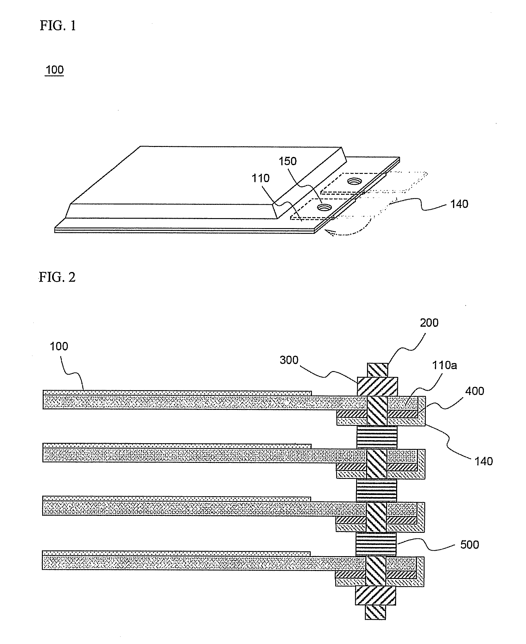
[0025]FIG. 1 is a perspective view typically illustrating an exemplary unit cell constituting a battery module according a preferred embodiment of the present invention.

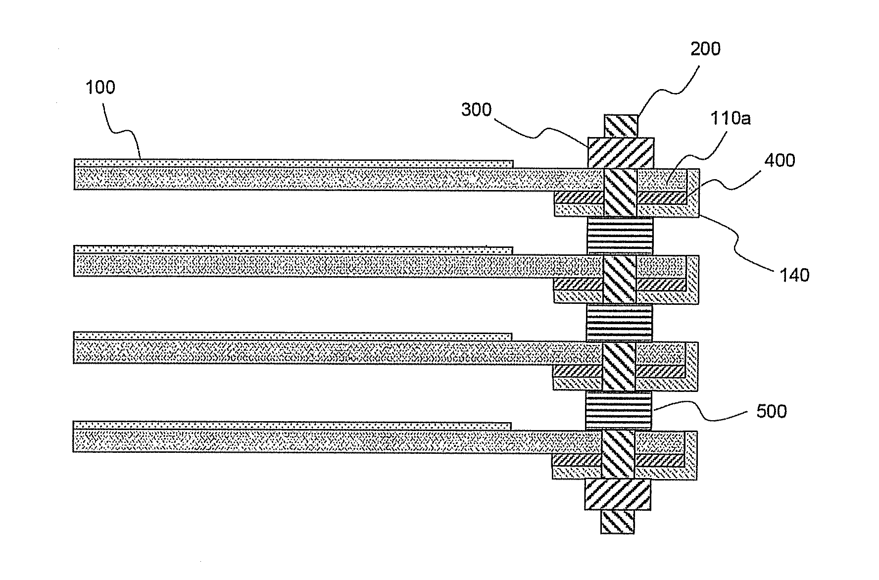
[0026] Referring to FIG. 1, a unit cell 100 includes an electrode assembly (not shown) of a cathode / separator / anode structure mounted in a pouch-shaped battery case made of an aluminum laminate sheet in a sealed state. Plate-shaped electrode leads 140 protrude from an upper-end sealing part 110a of the laminate sheet. The electrode leads 140 are bent downward and then placed on the lower-side surface of the upper-end sealing part 110a, as indicated by an arrow. Through-holes 150 are formed in the electrode leads 140 and the upper-end sealing part 110a such that the through...


PUM

PropertyMeasurementUnit
thicknessaaaaaaaaaa
thicknessaaaaaaaaaa
conductiveaaaaaaaaaa

Abstract

Disclosed herein is a battery module having a structure in which a plurality of batteries, each having an electrode assembly mounted in a battery case made of a laminate sheet including a metal layer and a resin layer, as unit cells, are stacked one on another in the thickness direction, wherein the battery module is constructed such that electrode leads of each unit cell are bent and placed on an upper-end sealing part of each unit cell, through-holes for mechanical coupling and electrical connection are formed in the electrode leads and the sealing part such that the through-holes of the electrode leads communicate with the corresponding through-holes of the sealing part, respectively, and conductive coupling members are inserted through the through-holes of the unit cells, respectively, whereby the electrical connection and the mechanical coupling are accomplished. The battery module having the novel structure according to the present invention has the effect of accomplishing the maximum reduction in volume of the battery module, increasing sealability of the sealing part, from which the electrode leads protrude, and easily accomplishing the electrical connection and the mechanical coupling between components constituting the battery module.

Description

FIELD OF THE INVENTION [0001] The present invention relates to a battery module having a structure in which a plurality of batteries, each having an electrode assembly mounted in a battery case made of a laminate sheet including a metal layer and a resin layer, as unit cells, are stacked one on another in the thickness direction, and, more particularly, to a battery module constructed such that electrode leads of each unit cell are bent and placed on an upper-end sealing part of each unit cell, through-holes for mechanical coupling and electrical connection are formed in the electrode leads and the sealing part such that the through-holes of the electrode leads communicate with the corresponding through-holes of the sealing part, respectively, and conductive coupling members are inserted through the through-holes of the unit cells, respectively, whereby the electrical connection and the mechanical coupling between components constituting the battery module are accomplished. BACKGROU...

Claims


Application Information

Patent Timeline
Patent Type & Authority Applications(United States)
IPC IPC(8): H01M2/08H01M6/46H01M50/529H01M50/186H01M50/211H01M50/531
CPCH01M2/0287H01M2/08H01M2/1077H01M2/26Y02E60/12Y02E60/10H01M50/124H01M50/531H01M50/186H01M50/211H01M50/20H01M50/543
Inventor YOU, SEUNGJAEKIM, SUNG-WOONAMGOONG, JOHN E.YU, JISANG
Owner LG ENERGY SOLUTION LTD
Why Eureka
Try Eureka