
Terminal-connecting means

a technology of connecting means and terminals, which is applied in the direction of coupling device connection, cell components, cell component details, etc., can solve the problems of not being able to fundamentally prevent the above-mentioned problems, and achieve the effect of preventing the complete separation of the cover and the connecting device body

Active Publication Date: 2006-11-02
LG ENERGY SOLUTION LTD
View PDF9 Cites 28 Cited by
  • Summary
  • Abstract
  • Description
  • Claims
  • Application Information

AI Technical Summary

Benefits of technology

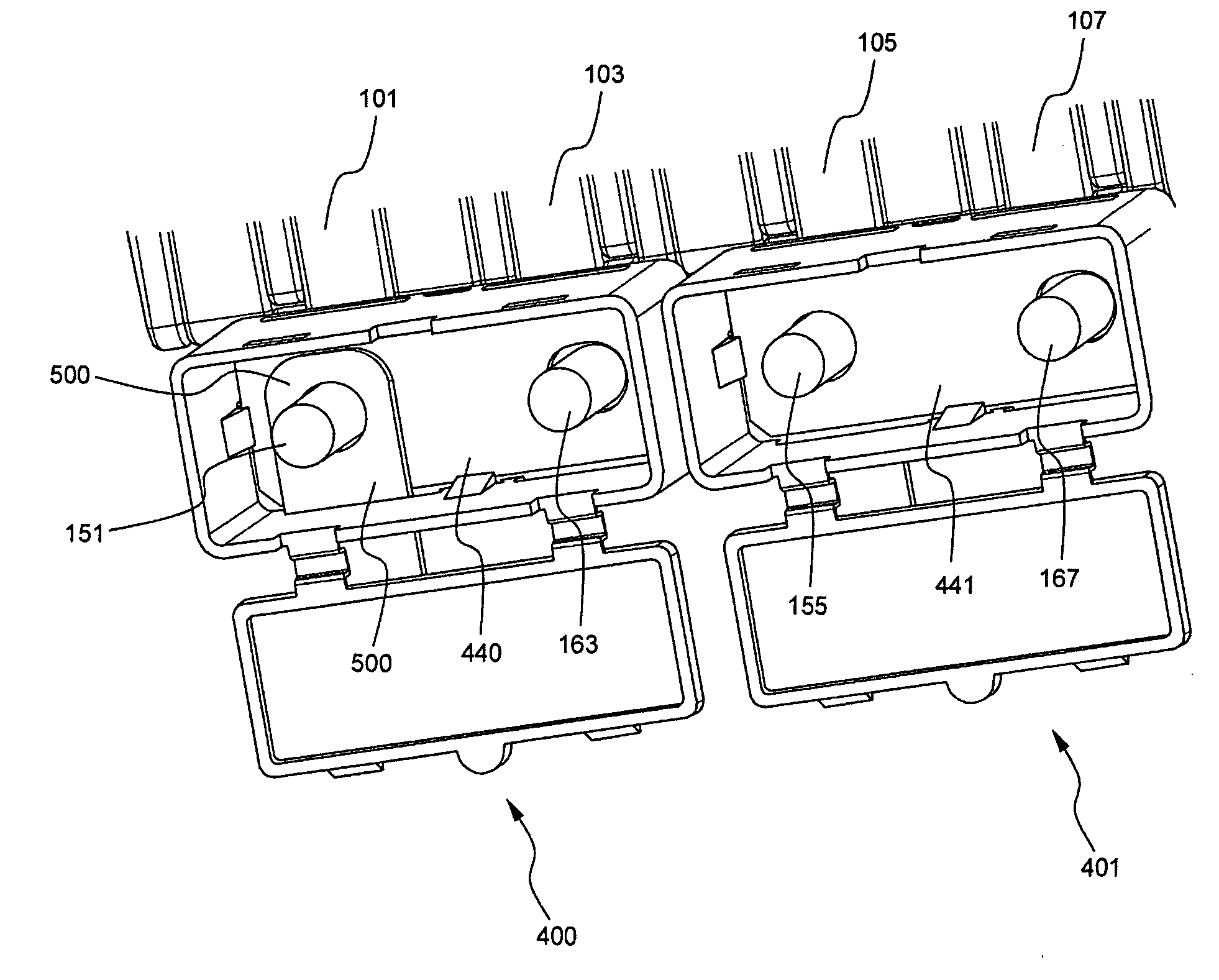
[0009] Specifically, it is an object of the present invention to provide a terminal-connecting device that is capable of easily accomplishing the electrical connection between electrode terminals.
[0010] It is another object of the present invention to provide a terminal-connecting device that is capable of isolating a terminal connection part from the outside, thereby preventing the occurrence of short circuits and protecting the terminal connection part from being corroded due to moisture.
[0011] It is yet another object of the present invention to provide a terminal-connecting device that is capable of having the above-mentioned effects even when an external connecting member is connected to the corresponding electrode terminal.
[0013] Consequently, when the electrode terminals are inserted into the terminal insertion holes formed in the lower end of the connecting device body of the terminal-connecting device according to the present invention, the electrode terminals are electrically connected with each other via the bus bar mounted to the lower end of the connecting device body, and therefore, the electrical connection is easily accomplished, and the terminal-connecting device according to the present invention can be easily removed as occasion demands. Also, the open upper end of the connecting device body is shielded by the cover such that the terminal connection part is isolated from the outside, and therefore, the occurrence of short circuits and the occurrence of corrosion due to moisture are effectively prevented. Furthermore, in the case that the external connecting member is to be electrically connected to the corresponding electrode terminal for the output of the power, the detection of voltage necessary to control the battery, or the electrical connection between the battery modules, the external connecting member can be inserted through the connecting member insertion slit, whereby the object of the present invention is accomplished. Even in this case, the effects due to the isolation of the connection part can also be obtained as described above.
[0016] The cover may be detachably coupled to the open upper end of the connecting device body. In a preferred embodiment, the cover is hingedly connected to one side of the connecting device body, whereby the complete separation of the cover from the connecting device body is prevented.
[0017] Also, the cover is provided with coupling protrusions, and the connecting device body is provided with coupling grooves, which correspond to the coupling protrusions of the cover, respectively, whereby the cover is prevented from being easily separated from the connecting device body due to external impacts after the cover is coupled to the connecting device body.

Problems solved by technology

Although some conventional apparatuses and methods for isolating the terminal connection part from the outside have been proposed, no apparatus that is capable of fundamentally preventing the above-mentioned problems has been developed yet.

Method used


Image

  • Terminal-connecting means
  • Terminal-connecting means
  • Terminal-connecting means

Examples


Embodiment Construction

[0028] Now, a preferred embodiment of the present invention will be described in detail with reference to the accompanying drawings. It should be noted, however, that the scope of the present invention is not limited by the illustrated embodiment.

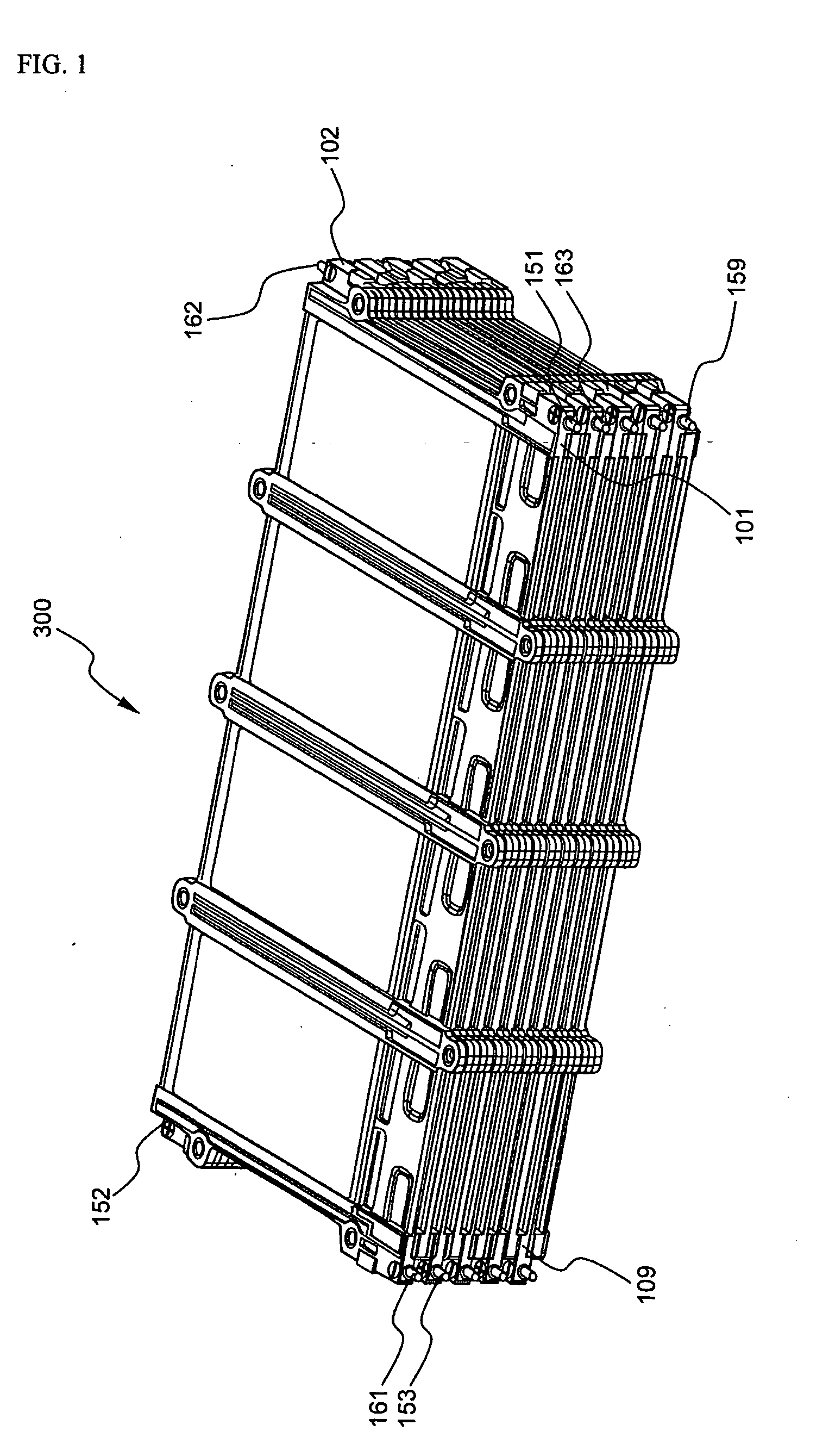
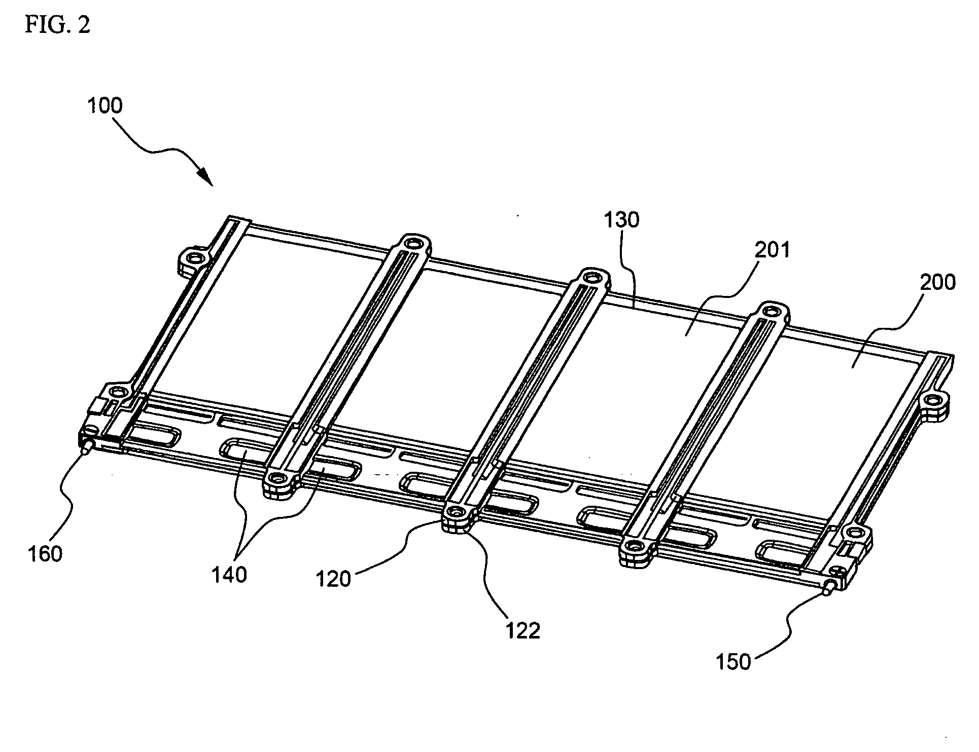
[0029]FIG. 1 is a partial perspective view typically illustrating an exemplary battery module, to which a terminal-connecting device according to the present invention can be applied, and FIG. 2 is a perspective view typically illustrating one of battery cartridges constituting the battery module shown in FIG. 1.

[0030] Referring to these drawings, the battery cartridge 100 comprises a pair of frames 120 and 122, which are attached to each other. Unit cells 200 and 201 are located between the frames 120 and 122 while the frames 120 and 122 are separated from each other, and are then securely fixed between the frames 120 and 122 after the frames 120 and 122 are attached to each other. The unit cell 200 has an electrode lead (not shown), whi...


PUM


Abstract

Disclosed herein is a terminal-connecting device including an electrically insulating hollow connecting device body having an open upper end, and an electrically insulating cover coupled to the open upper end of the connecting device body. The terminal-connecting device is constructed such that a plate-shaped conductive bus bar is mounted to the lower end of the connecting device body, two or more terminal insertion holes are formed in the lower end of the connecting device body and the bus bar, the terminal insertion holes formed in the lower end of the connecting device body communicating with the terminal insertion holes formed in the bus bar, and a connecting member insertion slit is formed in one side of connecting device body for allowing further connection of the corresponding electrode terminal to an external connecting member, as occasion demands. The electrical connection between the electrode terminals and the electrical connection between the external connecting member and the corresponding electrode terminal can be easily and conveniently accomplished through the use of the terminal-connecting device according to the present invention. Also, the terminal connection part is isolated from the outside, whereby the occurrence of short circuits and the occurrence of corrosion due to moisture are effectively prevented. The terminal-connecting device according to the present invention is preferably used in manufacturing a medium- or large-sized battery system, especially, for electric vehicles and hybrid electric vehicles.

Description

FIELD OF THE INVENTION [0001] The present invention relates to a terminal-connecting device, and, more particularly, to a terminal-connecting device that is capable of accomplishing the electrical connection between batteries, the electrical connection between battery cartridges, the electrical connection between the terminals of other power supplies, or the electrical connection between an external connecting member and the corresponding electrode terminal, thereby accomplishing easy connection and preventing the connection part from being exposed to the outside, and therefore, preventing the occurrence of short circuits and protecting the connection part from being corroded due to foreign matter. BACKGROUND OF THE INVENTION [0002] Recently, a secondary battery, which can be charged and discharged, has been widely used as an energy source for wireless mobile devices. Also, the secondary battery has attracted considerable attention as a power source for electric vehicles and hybrid ...

Claims


Application Information

Patent Timeline
IPC IPC(8): H01R24/00H01M50/505
CPCH01M2/202Y02E60/10H01M50/505
Inventor YOON, JUNILLRO, JONG-YULJUNG, DO YANGYOON, YEO WON
Owner LG ENERGY SOLUTION LTD
Learn More