Full automatic relief device for automobile
A fully automatic and automotive technology, applied in the direction of auxiliary wheels/rings, etc., can solve the problems of cumbersome and inconvenient installation process, easy to dirty clothes, and harsh environment
- Summary
- Abstract
- Description
- Claims
- Application Information
AI Technical Summary
Problems solved by technology
Method used
Image


Examples
Embodiment 1
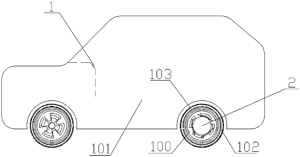
[0032] Such as Figure 1 to Figure 3 As shown, a fully automatic car escape device corresponding to a preferred embodiment of the present invention includes: a starting device 1 and an escape module 2, and the starting device 1 can be integrated on the dashboard surface of the car and on the remote control key of the car to get out of trouble. The module 2 has been locked on the vehicle wheel hub 100 by screws when the car leaves the factory, and there is no need for later installation. The four wheel hubs 100 of the car can be equipped with the escape module 2, and the starting device 1 can control each escape module 2 to start or close.
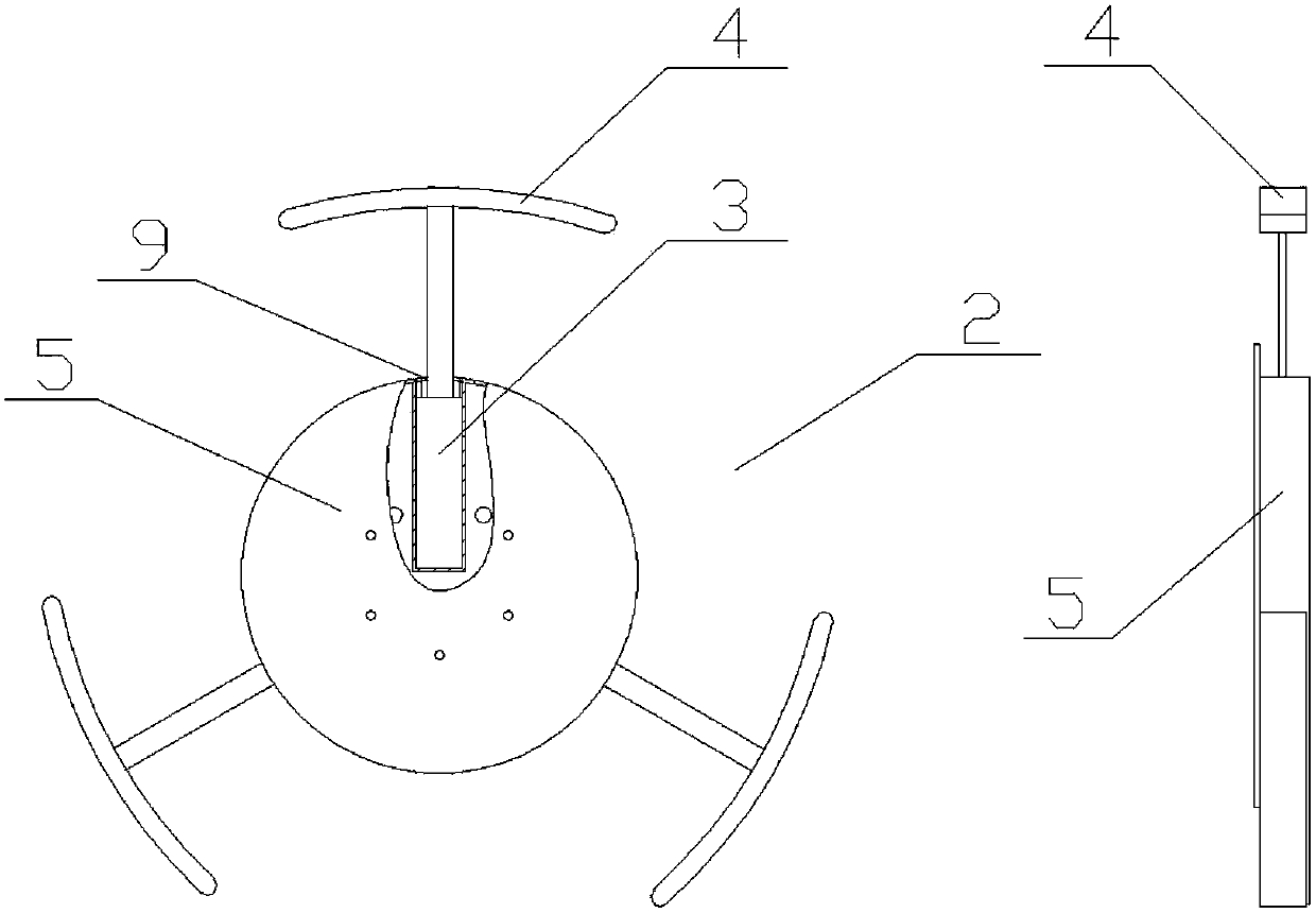
[0033] The escape module 2 includes a mounting frame 5, a telescoping mechanism 3 and a plug 4. The mounting frame 5 is a flat cylindrical shape, which is connected to the hub 100 by screws, and has a plurality of holes leading to its axis on the side of the mounting frame 5. The mounting hole 9, the telescopic mechanism 3 is installed in t...
Embodiment 2
[0037] Such as Figure 4 to Figure 6 As shown, it corresponds to another embodiment of the automatic vehicle escape device of the present invention, including: a starting device 1 , an escape module 2 and a mechanical arm 6 . The starting device 1 is the same as in Embodiment 1, and can be arranged on the dashboard surface of the car and the remote control key of the car. The mechanical arm 6 has multiple degrees of freedom, and is installed inside the vehicle, preferably at a position close to the tire 102. A through hole 10 for the mechanical arm 6 to enter and exit and a sealing cover 12 that can seal the through hole 10 need to be provided on the vehicle body. A mechanism (not shown) for automatically ejecting and retracting is provided between the sealing cover 12 and the vehicle body. When the mechanical arm 6 stretches out, the sealing cover 12 is automatically opened, and after the mechanical arm 6 is retracted, the sealing cover 12 can be automatically closed. The me...
Embodiment approach
[0051] Such as Figure 10 As shown, the third embodiment of the present invention is substantially the same as Embodiment 2, except that the telescopic mechanism 3 includes a radial telescopic mechanism 7 and an axial telescopic mechanism 8, and the radial telescopic mechanism 7 and the axial telescopic mechanism 8 are perpendicular to each other. It is provided that the axial telescopic mechanism 8 is connected with the plug 4 for pushing the plug 4 to the outer peripheral surface of the tire 102 .
[0052] Under this kind of embodiment, the step of moving the plug 4 to the outer peripheral surface of the tire 102 by the mechanical arm 6 (that is, the step 3 of starting the action process in Embodiment 2) or the step of removing the outer peripheral surface of the tire 102 (that is, the retracting action in the second embodiment) Step 2) of the process is accomplished by the axial telescoping mechanism 8 . The radial telescopic mechanism 7 is used to extend or retract the ax...
PUM
 Abstract
Description
Claims
Application Information
 - R&D
- Intellectual Property
- Life Sciences
- Materials
- Tech Scout
- Unparalleled Data Quality
- Higher Quality Content
- 60% Fewer Hallucinations
Browse by: Latest US Patents, China's latest patents, Technical Efficacy Thesaurus, Application Domain, Technology Topic, Popular Technical Reports.
© 2025 PatSnap. All rights reserved.Legal|Privacy policy|Modern Slavery Act Transparency Statement|Sitemap|About US| Contact US: help@patsnap.com