A centrifugal wire unfolding mechanism

A technology of deploying the mechanism and centrifugal type, which is applied in the field of micro-nano satellites, can solve the problems of insufficient thrust of the device, achieve the effect of simplifying the complexity of the mechanism structure and saving the space volume of the mechanism

Active Publication Date: 2019-06-18
BEIJING INST OF CONTROL ENG
View PDF6 Cites 0 Cited by
  • Summary
  • Abstract
  • Description
  • Claims
  • Application Information

AI Technical Summary

Problems solved by technology

[0004] The technical problem of the present invention is: to overcome the deficiencies of the prior art, and propose an off-line wire deployment mechanism, which can solve the problem of insufficient device thrust in the traditional electric sail propulsion technology, and at the same time, the structure of each device in the electric sail deployment mechanism will not intertwined, intertwined

Method used


Image

  • A centrifugal wire unfolding mechanism
  • A centrifugal wire unfolding mechanism
  • A centrifugal wire unfolding mechanism

Examples


Embodiment Construction

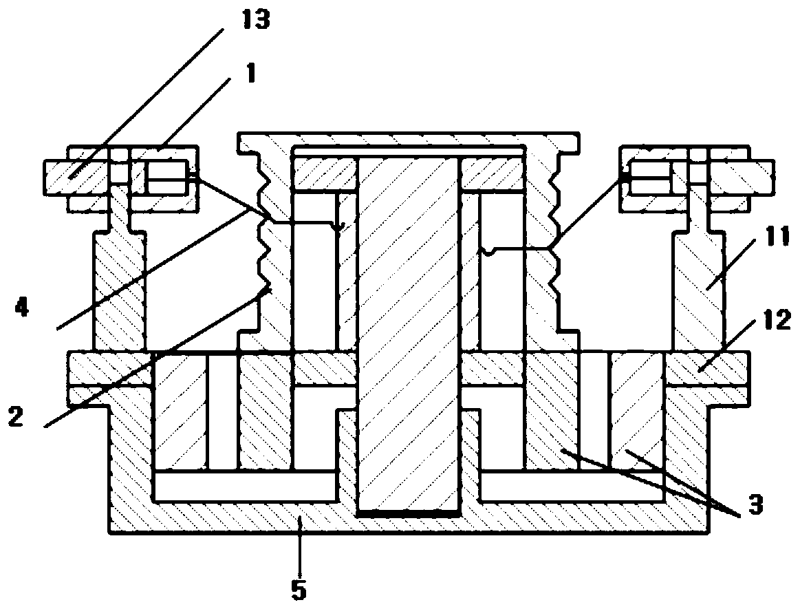
[0023] like figure 1 A centrifugal wire unfolding mechanism is shown, including a locking device 1, a bobbin device assembly 2, a stepping motor 3, an electric sail wire 4, and a device base 5, and the stepping motor 3 is installed on the device base 5 At the bottom of both sides, the spool device assembly 2 is installed in the middle of the bottom of the device base 5, above the four stepping motors 3 on the inner side, fixed by the bearing assembly, the electric sail wire 4 is wound on the spool device assembly, four locks The tightening device 1 is respectively installed at the midline position of the four edges of the device base 5. The locking device 1 is divided into a pull-out electromagnet 11, a support 12 and an end mass block 13. A section of the electric sail wire 4 is respectively connected to each lock. On the end mass 13 of the tightening device 1; before the unfolding mechanism is powered on, the unlocking of the device is completed, the stepper motor 3 starts t...


PUM


Abstract

Disclosed is a centrifugal type wire unwinding mechanism. The centrifugal type wire unwinding mechanism is used for supplying power for unwinding of an electric sail wire in an electric sail unwindingmechanism and providing a reliable unwinding scheme. The centrifugal type wire unwinding mechanism comprises a locking device, a bobbin device assembly, a stepping motor, the electric sail wire and adevice base. According to the centrifugal type wire unwinding mechanism, the problem that as for an existing electric sail propulsion technology, thrust is insufficient due to thin space particles issolved; the special structural characteristic of the electric sail wire can be overcome, and twisting of the wire and hooking of the wire and other satellite assemblies in the unwinding process can be avoided; and structural stability is high, and reliability and stability in the unwinding process are guaranteed.

Description

technical field [0001] The invention belongs to the field of micro-nano satellites, and relates to a centrifugal wire deployment mechanism, which is mainly used in the deployment of a slip ring device in the electric sail deployment mechanism that supplies power to the electric sail wire mechanism. Background technique [0002] In the field of micro-nano satellites, electric sail propulsion technology is a propellant-free propulsion technology. Electric sail has the advantages of no propellant, high thrust, high efficiency, low power consumption, and 24-hour uninterrupted continuous work. The electric sail propulsion system is mainly composed of electric sail wires, electron guns, and deployment mechanisms. Among them, the positively charged wires of the electric sail form a virtual sail surface through the electric field, repel the protons in the space solar wind, make it deviate from the original trajectory, and generate thrust through momentum exchange; high positive pot...

Claims


Application Information

Patent Timeline
Patent Type & Authority Patents(China)
IPC IPC(8): B64G1/22B64G1/40
CPCB64G1/222B64G1/40
Inventor 王斌刘继奎张强李睿于洋朱林林刘雪鹏刘巍王术席同鑫
Owner BEIJING INST OF CONTROL ENG
Why Eureka
Try Eureka