
Solenoid valve with long service life

A solenoid valve with a long service life technology, applied in the field of solenoid valves, can solve problems such as inconvenient maintenance, valve core wear, and reduced service life of solenoid valves, and achieve the effects of convenient installation and disassembly, improved service life, and increased service life

Active Publication Date: 2018-02-02
无锡正大轴承机械制造股份有限公司
View PDF5 Cites 7 Cited by
  • Summary
  • Abstract
  • Description
  • Claims
  • Application Information

AI Technical Summary

Problems solved by technology

[0002] Solenoid valve is a common industrial equipment used to realize electromagnetic control, and its application is more and more widely; Closed; when the solenoid is energized, the valve core leaves the valve port, compresses the spring, and the solenoid valve opens; this kind of solenoid valve needs to install a spring in the through hole of the valve core, the structure is relatively complicated, and the requirements for the spring are relatively high, and the second is the service time of the spring. After a long time, it is easy to deform, which seriously affects the sealing between the valve core and the valve port. The spring is especially easy to be damaged when the solenoid valve is frequently opened and closed, which seriously affects the service life of the solenoid valve.
The spool and seat of the existing solenoid valve are also prone to offset, which will cause severe wear of the spool and reduce the service life of the solenoid valve after prolonged use; in addition, the installation and disassembly of the existing solenoid valve are also relatively difficult. easy maintenance

Method used


Image

  • Solenoid valve with long service life

Examples


Embodiment Construction

[0018] The following will clearly and completely describe the technical solutions in the embodiments of the present invention with reference to the accompanying drawings in the embodiments of the present invention. Obviously, the described embodiments are only some, not all, embodiments of the present invention. Based on the embodiments of the present invention, all other embodiments obtained by persons of ordinary skill in the art without making creative efforts belong to the protection scope of the present invention.

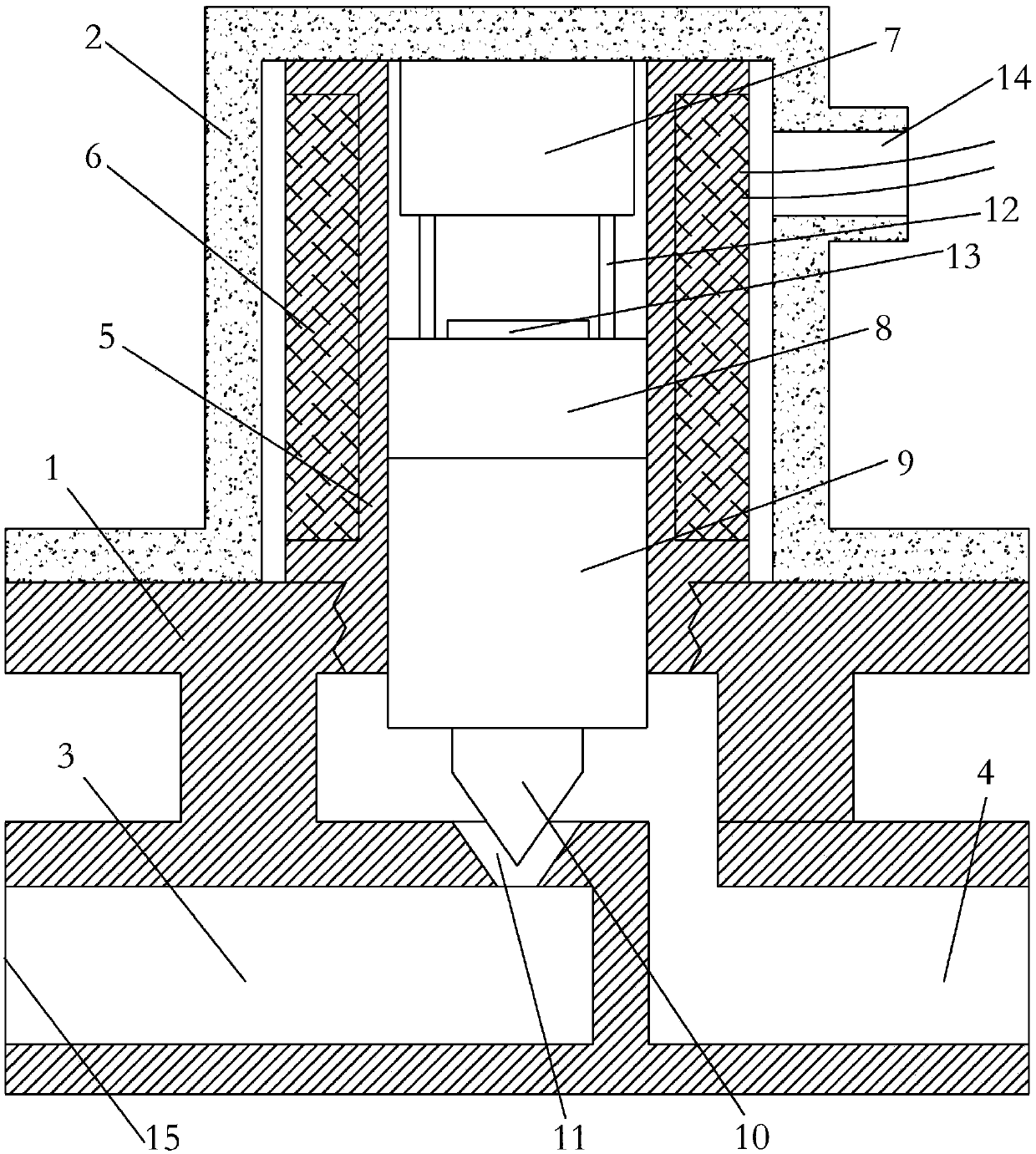
[0019] The object of the present invention is to provide a solenoid valve with long service life to solve the problems in the prior art, increase the service life of the solenoid valve, and make the solenoid valve easy to install and disassemble.

[0020] The invention provides a solenoid valve with long service life, which includes a valve seat, a coil frame arranged on the valve seat, and a valve cover arranged outside the coil frame and connected to the valv...


PUM


Abstract

The invention discloses a solenoid valve with a long service life. The solenoid valve comprises a valve seat, a coil rack arranged on the valve seat and a valve cover arranged on the coil rack in a covering mode and connected to the valve seat. The valve seat is internally provided with a buffer cavity communicating with an inner cavity of the coil rack and further internally provided with a liquid inlet pipe and a liquid outlet pipe which communicate with the buffer cavity, and the liquid inlet pipe and the buffer cavity communicate through a through hole formed opposite to an inner cavity ofthe coil rack; a coil is wound outside the coil rack, and an iron core is slidably arranged inside the coil rack; the end, close to the through hole, of the iron core is fixedly provided with a valvecore, and the end, close to the valve cover, of the iron core is fixedly provided with a first permanent magnet; and a second permanent magnet which is repellent to the first permanent magnet is fixedly arranged at the top of an inner cavity of the valve cover. According to the solenoid valve with the long service life, a spring in a traditional solenoid valve is simplified so that the structureof the solenoid valve can be simple, the situation that the solenoid valve is used for long time, then a spring is prone to deforming, and the service life of the solenoid valve is affected accordingly does not exist, and thus the service life of the solenoid valve is greatly prolonged.

Description

technical field [0001] The invention relates to the technical field of valves, in particular to an electromagnetic valve with long service life. Background technique [0002] Solenoid valve is a common industrial equipment used to realize electromagnetic control, and its application is more and more widely; Closed; when the solenoid is energized, the valve core leaves the valve port, compresses the spring, and the solenoid valve opens; this kind of solenoid valve needs to install a spring in the through hole of the valve core, the structure is relatively complicated, and the requirements for the spring are relatively high, and the second is the service time of the spring. After a long time, it is easy to deform, which seriously affects the sealing between the valve core and the valve port. The spring is particularly easy to be damaged when the solenoid valve is frequently opened and closed, which seriously affects the service life of the solenoid valve. The spool and seat o...

Claims


Application Information

Patent Timeline
Patent Type & Authority Applications(China)
IPC IPC(8): F16K31/08F16K31/06F16K1/00
CPCF16K31/0655F16K31/082
Inventor 张国伟
Owner 无锡正大轴承机械制造股份有限公司
Learn More