Supercharge Your Innovation With Domain-Expert AI Agents!

Light module

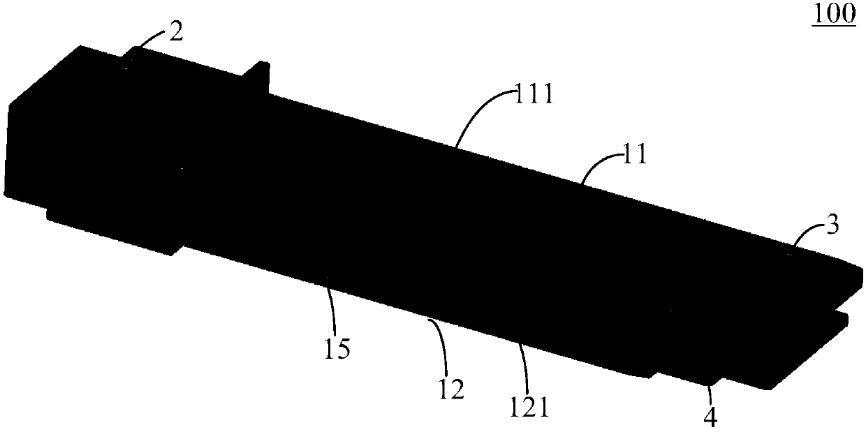
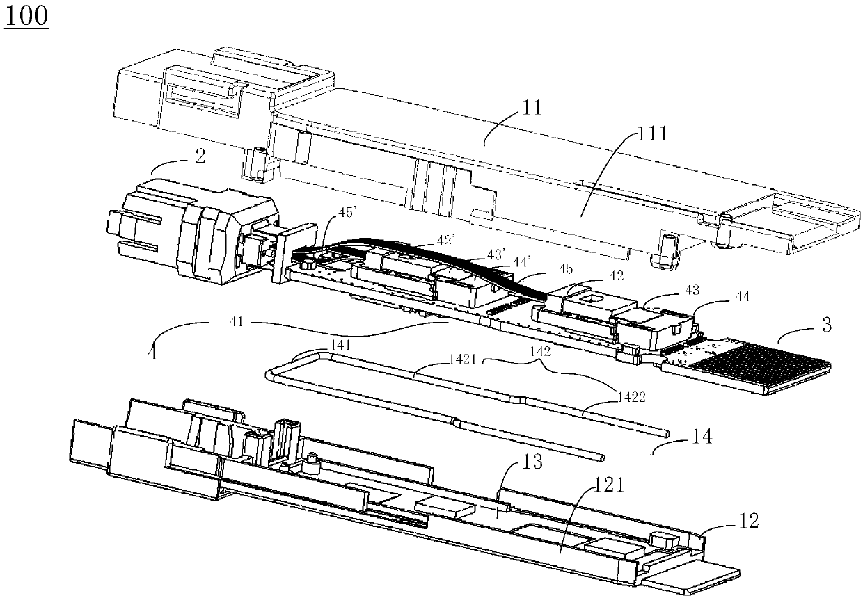
An optical module and optical interface technology, applied in the field of optical communication, can solve the problems of optical module performance degradation, data transmission error, electromagnetic leakage, etc., and achieve the effect of reducing electromagnetic interference, strengthening sealing, and solving electromagnetic interference problems.

Active Publication Date: 2018-02-02
HISENSE BROADBAND MULTIMEDIA TECH
View PDF3 Cites 5 Cited by
  • Summary
  • Abstract
  • Description
  • Claims
  • Application Information

AI Technical Summary

Problems solved by technology

[0004] However, while ensuring the high rate of the optical module, it is necessary to ensure that the optical module has a large transmit power and receive power, which creates another problem: Electromagnetic Interference (EMI), which easily causes the performance of the optical module to decline. resulting in data transmission errors
However, there is inevitably a gap between the docked first shell and the second shell, resulting in electromagnetic leakage

Method used


Image

  • Light module
  • Light module
  • Light module

Examples


Embodiment Construction

[0024] Reference will now be made in detail to exemplary embodiments, examples of which are illustrated in the accompanying drawings. When the following description refers to the accompanying drawings, the same numerals in different drawings refer to the same or similar elements unless otherwise indicated. The implementations described in the following exemplary examples do not represent all implementations consistent with the present disclosure. Rather, they are merely examples of apparatuses and methods consistent with aspects of the present disclosure as recited in the appended claims.

[0025] It should be noted that when an element is referred to as being “fixed” to another element, it can be directly on the other element or there can also be an intervening element. When an element is referred to as being "connected to" another element, it can be directly connected to the other element or intervening elements may also be present. As used herein, the terms "vertical", "h...


PUM


Abstract

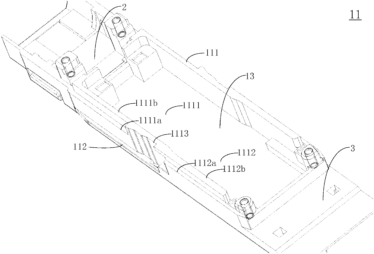
The invention relates to a light module. The light module comprises a first shell, a second shell, conducting adhesive tapes, a light interface part, an electricity interface part and a light module core part, wherein the first shell comprises a first bottom surface and first side walls positioned on two sides of the first bottom surface; the second shell comprises a second bottom surface and second side walls positioned on two sides of the second bottom surface, the first side walls are embedded into the second side walls and are in contact with the second bottom surface so as to form a hollow cavity; the conducting adhesive tapes are positioned inside the hollow cavity, and are arranged at the contact positions of the first side walls and the second bottom surface; the light interface part is positioned at one end of the hollow cavity; the electricity interface part is positioned at the other end, away from the light interface part, of the hollow cavity; and the light module core part is positioned inside the hollow cavity, and is connected with the light interface part through a light signal and the electricity interface part through an electricity signal. The shell sealing performance of the light module can be strengthened by adopting the light module, and the electromagnetic interference shielding effect is strengthened, so that the electromagnetic interference is effectively reduced.

Description

technical field [0001] The present disclosure relates to the technical field of optical communication, in particular to an optical module. Background technique [0002] With the rapid development of optical fiber communication technology, the application scenarios of optical modules, an important part of optical fiber communication, are becoming more and more complex, and users have higher and higher requirements for the performance and indicators of optical modules. [0003] When the optical module is actually used in a communication system, when the data flow transmitted between the optical module and the host (such as a switch or a base station) is very large, in order to ensure data transmission efficiency, the optical module usually needs to have a higher optical module rate. [0004] However, while ensuring the high rate of the optical module, it is necessary to ensure that the optical module has a large transmit power and receive power, which creates another problem: ...

Claims


Application Information

Patent Timeline
IPC IPC(8): H05K9/00H04B10/40
CPCH04B10/40H05K9/0015H05K9/0058
Inventor 郑龙
Owner HISENSE BROADBAND MULTIMEDIA TECH
Features
  • R&D
  • Intellectual Property
  • Life Sciences
  • Materials
  • Tech Scout
  • Unparalleled Data Quality
  • Higher Quality Content
  • 60% Fewer Hallucinations
Learn More