Eureka AIR delivers breakthrough ideas for toughest innovation challenges, trusted by R&D personnel around the world.

Connecting Element For Contacting A Shielding Of A Power Cable

A technology for connecting elements and contact elements, applied in the directions of electrical elements, conductive connections, electrical connection seats, etc., can solve the problems of high rigidity, deteriorated electrical contact, etc., and achieve the effect of flexible structure, low ohmic resistance, and simple outline

Active Publication Date: 2018-02-02
TYCO ELECTRONICS RAYCHEM GMBH A GERMAN CO
View PDF14 Cites 0 Cited by
  • Summary
  • Abstract
  • Description
  • Claims
  • Application Information

AI Technical Summary

Problems solved by technology

However, this arrangement has the disadvantage that the rigidity of the contact element 902 is rather high, so that when mounted on the cable, the contact element tends to protrude outwards
While this is no problem for arrangements where the contact element is located below the cable shield and protrusions are provided on the outer surface of the contact element, the rigidity leads to deterioration in arrangements where the contact element surrounds the cable shield and the same type of fixing element is used electrical contact

Method used


Image

  • Connecting Element For Contacting A Shielding Of A Power Cable
  • Connecting Element For Contacting A Shielding Of A Power Cable
  • Connecting Element For Contacting A Shielding Of A Power Cable

Examples


Embodiment Construction

[0053] The invention will now be further explained with reference to the accompanying drawings, first with reference to figure 1 . figure 1 Shown according to the present invention as a connecting element 100 ( Figure 5 A plan view of a part of the contact element 102 shown in FIG.

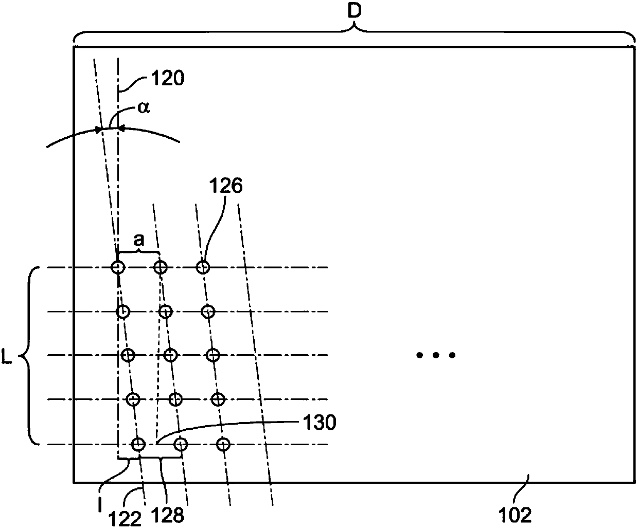
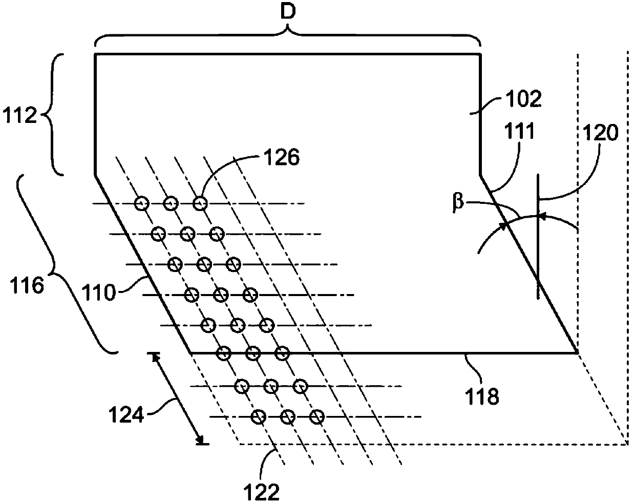
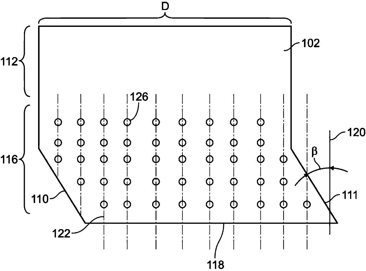
[0054] now refer to figure 1 , the contact element 102 according to the first aspect of the invention will be explained. According to this embodiment, the protrusions 126 are arranged in rows 122 at an angle α to the longitudinal axis 120 of the cable. The shape of the protrusion 126 can vary. The standard shape has a square profile and four triangular uprights (see Figure 8 ). exist Figures 1 to 4 In , protrusions are schematically represented by circular outlines. However, it needs to be recognized that this form is merely an example of forming the protrusion 126 .

[0055] Furthermore, it is expected that the connection element 100 according to the present invention can be used w...


PUM


Abstract

The present invention relates to connecting element which is used for contacting an electrically conductive shield of a cable. A connecting element (100) for contacting a shielding layer or a plurality of shielding wires of a power cable according to the present invention comprises an electrically conductive contact element (102) for electrically contacting said shielding. Said contact element (102) comprises a plurality of contact protrusions (126) which in a mounted state protrude towards the shielding, said contact protrusions (126) being arranged in a plurality of rows (122) which have a distance from each other that extends, in a mounted state, circumferentially around said cable and a length that extends along said cable. Said rows (122) are arranged in a way that they form an angle(a) unequal zero with a longitudinal axis (120) of the cable.

Description

technical field [0001] The invention relates to a connection element for contacting a conductive shield, in particular a shield or a plurality of shielded wires of a cable, for connecting it to a conductive shield of another cable and / or directly to earth. Background technique [0002] Cable assemblies used to transmit large amounts of electrical power are usually made of single-core cables with metal sheaths or other forms of ground return conductors usually surrounded by an electrically insulating outer sheath made of plastic material in most cases. Sleeve (or protective sleeve) to avoid uncontrolled grounding (connection to ground) and to protect the conductor from corrosion. [0003] The cable shield (the metal barrier that surrounds the cable insulation) keeps the outside of the cable at or near ground potential. It also provides a path for loop currents and fault currents. Shielding also protects cables from lightning strikes and current from other fault sources. Me...

Claims


Application Information

Patent Timeline
IPC IPC(8): H01R4/26H01R11/28
CPCH01R4/26H01R11/28H01R9/0512H01R9/0518H01R4/188H01R13/6592
Inventor T.西蒙松B.韦尔
Owner TYCO ELECTRONICS RAYCHEM GMBH A GERMAN CO
Why Eureka
Eureka Blog
Learn More