Torsion spring for electro-mechanical switches and a cantilever-type RF micro-electromechanical switch incorporating the torsion spring

a technology of electro-mechanical switches and torsion springs, which is applied in the field of micro-electro-mechanical switches and high-power rf mems, can solve the problems of high isolation value, insertion losses, and high loss of pin diodes and transistors, and achieves improved electrical contact, less heating, and increased durability.

Inactive Publication Date: 2005-01-25
HRL LAB
View PDF19 Cites 8 Cited by
  • Summary
  • Abstract
  • Description
  • Claims
  • Application Information

AI Technical Summary

Benefits of technology

The present invention solves this and other problems by providing a torsion spring which is configured to result in a substantially conformal contact between the contact plates. The resultant MEMS has increased durability, and because the substantially conformal contact results in a better electrical contact, there is less heating and the MEM switch can handle more power. Thus, a more durable and versatile MEM switch results.
One embodiment of the present invention provides an armature mounted torsion spring, wherein the torsion spring is configured to provide sufficient flexibility such that when an armature electrode is electromechanically brought into contact with a substrate electrode the electrodes provide substantial conformity with one another and thus maximize contact area, reduce wear and reduce Ohmic resistance.
This invention provides a new RF MEM switch in which the RF line is loaded with a torsion spring to achieve a conformal metal to metal contact. A conformal metal to metal contact assures a maximum contact area and lowest contact resistance, and, therefore, provides for critical long term reliability and good heat dissipation thus allowing for improved high-power handling.
Another embodiment of the present invention provides an armature for a micro-electro-mechanical switch having a torsion spring. The armature comprises a first beam structural layer having a first end for mechanically connecting with a substrate of a micro-electro-mechanical switch and a second end including a set of tines including at least one tine. A terminus portion is suspended between the tines, and includes a conducting transmission line configured to be positioned over the input and output lines of a micro-electro-mechanical switch. At least a portion of the conducting transmission line is exposed for conformal contact with the input and output lines. An armature electrode is directly above a substrate electrode of the micro-electro-mechanical switch and suspended on the armature, and an insulating layer is positioned between the armature electrode and the substrate electrode to prevent short-circuiting therebetween when the armature is assembled in a micro-electro-mechanical switch and actuated into a closed position. When the armature is assembled in a micro-electro-mechanical switch and is actuated into a “closed” position, the terminus is free to rotate to ensure a conformal contact between the exposed portion of the conducting transmission line and the input and output lines in order to form a circuit therebetween to permit the flow of electricity.

Problems solved by technology

At microwave frequencies, however, these devices suffer from several shortcomings.
Pin diodes and transistors typically have an insertion loss greater than 1 dB, which is the loss across the switch when the switch is closed.
In addition, the insertion losses and high isolation value for these switches vary depending on the frequency of the signal passing through the switches.
These characteristics make semiconductor transistors and pin diodes a poor choice for switches in microwave applications.
In addition, the switch has a large frequency response and a large bandwidth compared to semiconductor transistors and pin diodes.
Micro-electromechanical switches of the general type described above are, however, prone to premature failure.
The cause of the premature failure is linked to the damage resulting from the impact of the armature contact with the substrate contact.
This damage is exacerbated by the fact that conventional MEM switches have armature contacts that impinge on the substrate contact surface at an angle.
The angled impact results in all the impact energy being transferred to a relatively small area, thereby ultimately causing premature failure due to both increased impact per unit area and heat caused by resistive heating due to increased current density through the small area of actual contact.

Method used


Image

  • Torsion spring for electro-mechanical switches and a cantilever-type RF micro-electromechanical switch incorporating the torsion spring
  • Torsion spring for electro-mechanical switches and a cantilever-type RF micro-electromechanical switch incorporating the torsion spring
  • Torsion spring for electro-mechanical switches and a cantilever-type RF micro-electromechanical switch incorporating the torsion spring

Examples


Embodiment Construction

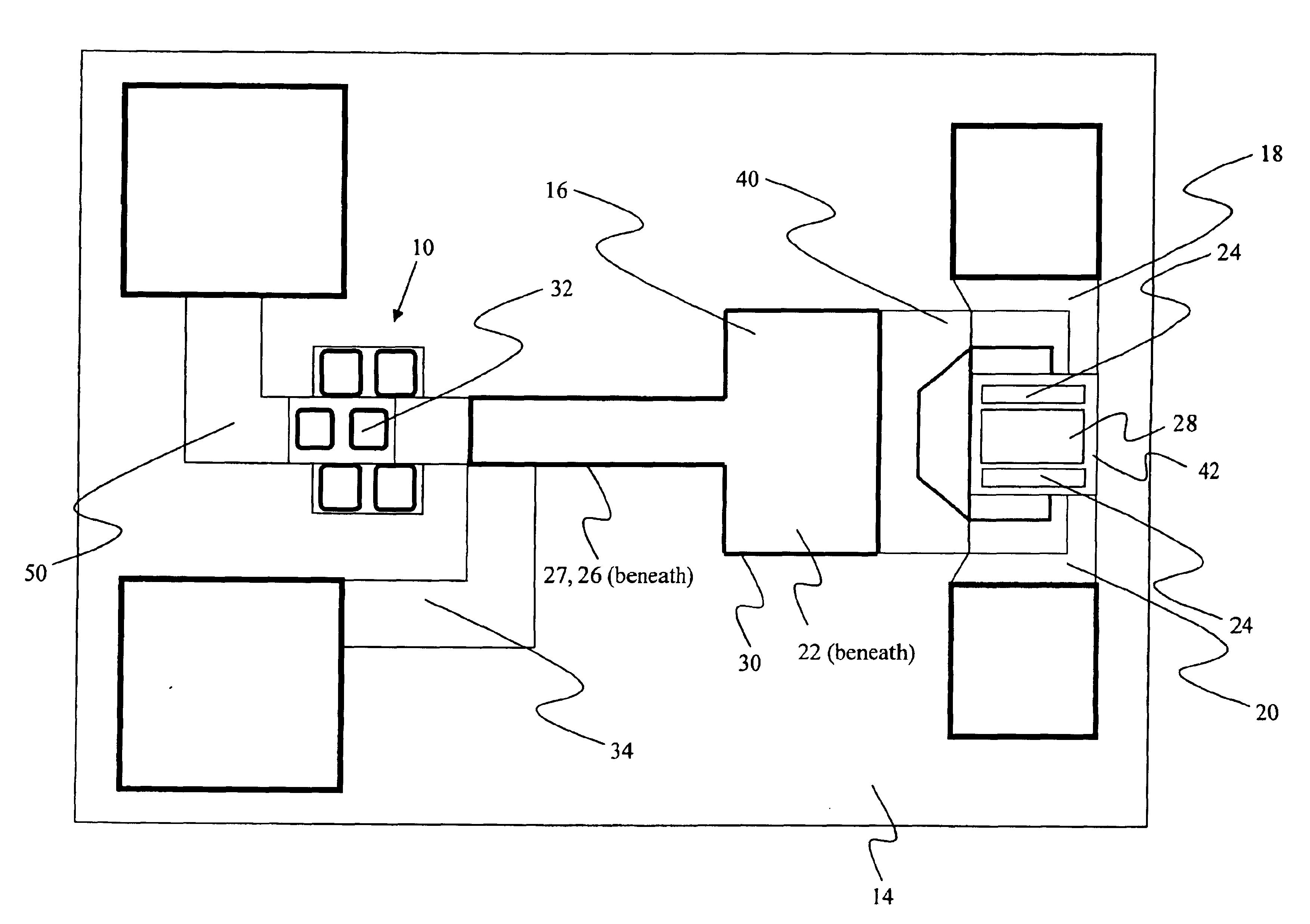
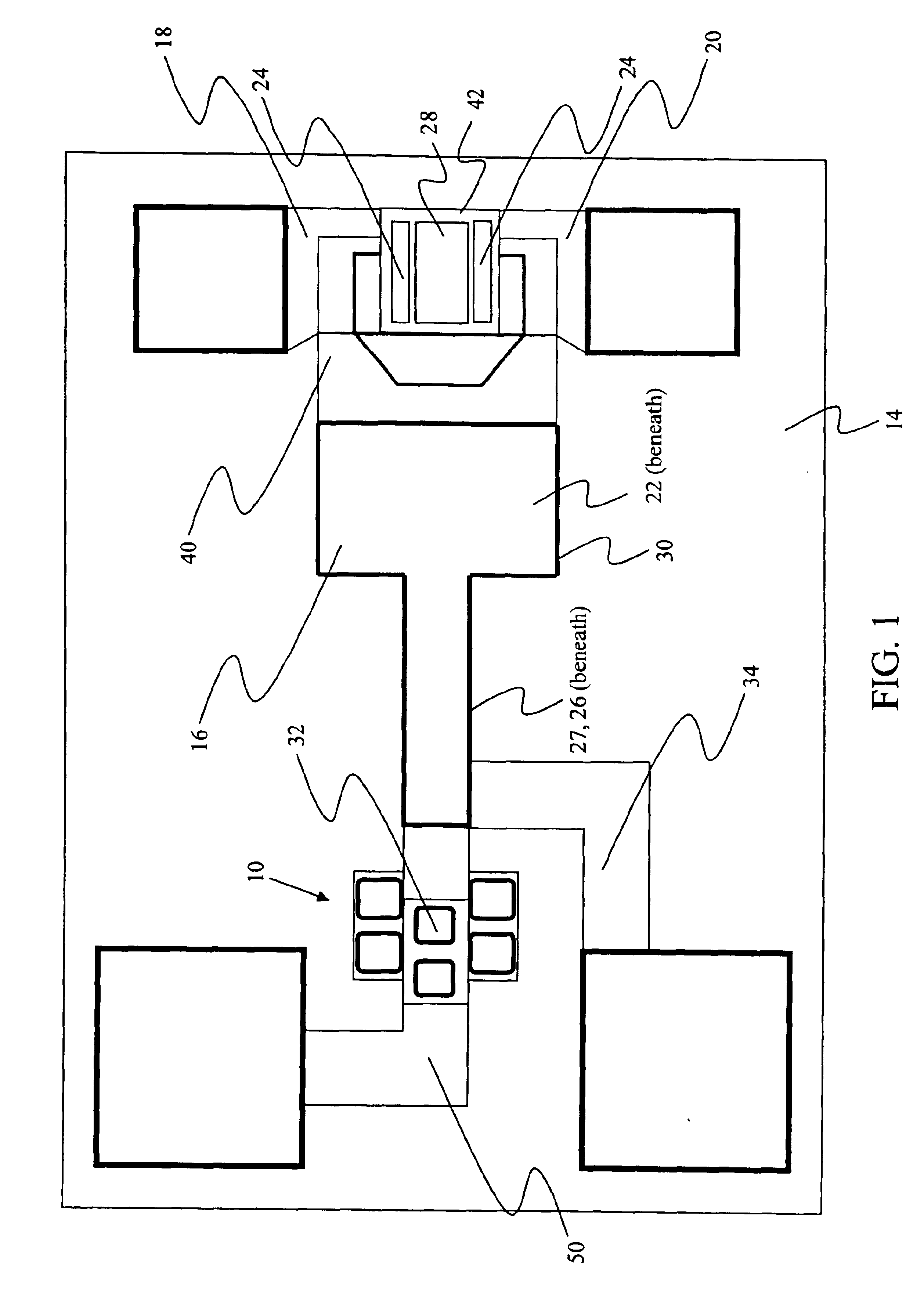
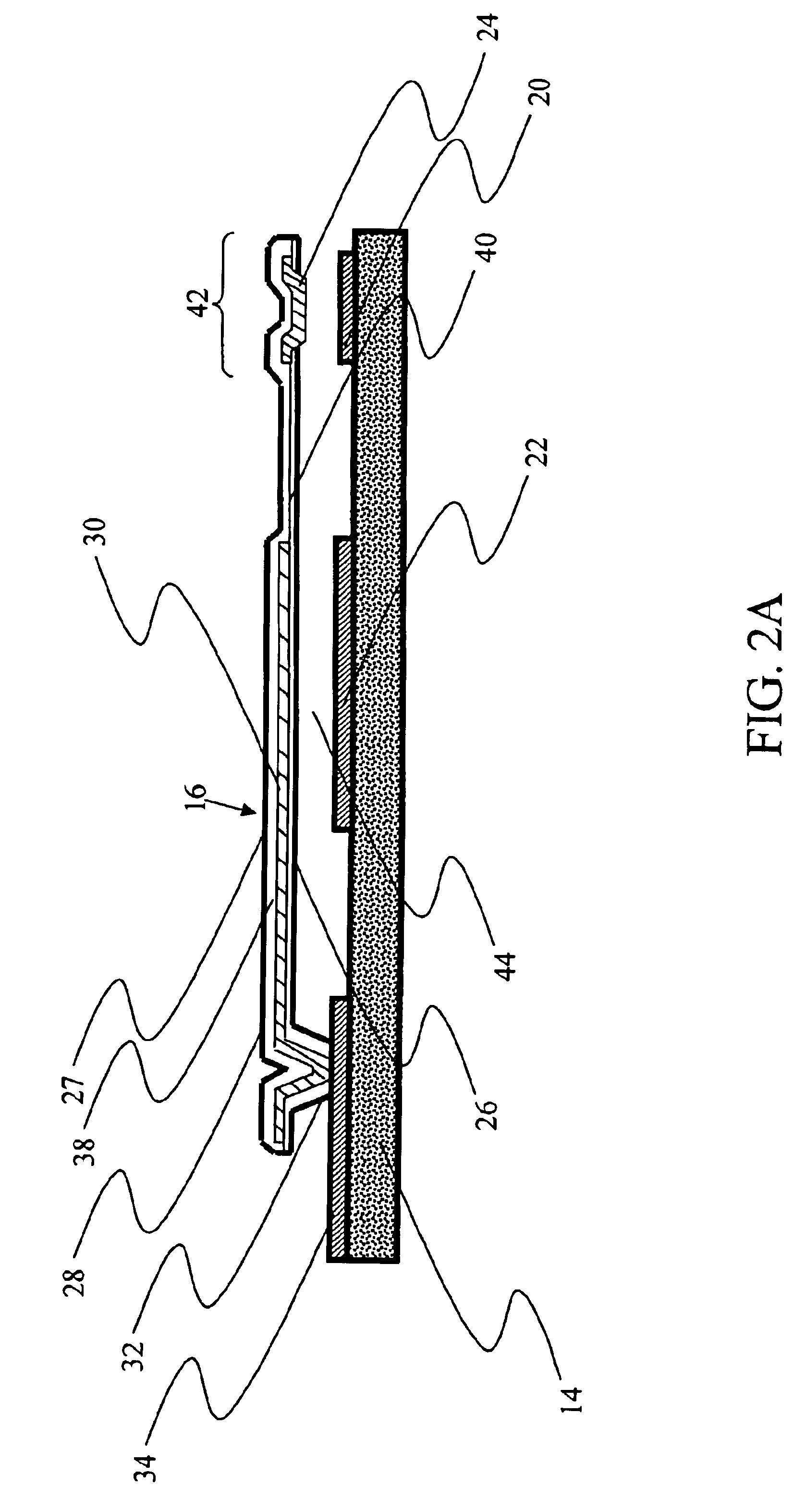
The present invention generally relates to electro and micro-electro-mechanical switches (MEMS), and more particularly to a torsion spring for providing improved input / output contact in high power RF MEMS. The following description, taken in conjunction with the referenced drawings, is presented to enable one of ordinary skill in the art to make and use the invention and to incorporate it in the context of particular applications. Various modifications, as well as a variety of uses in different applications, will be readily apparent to those skilled in the art, and the general principles defined herein, may be applied to a wide range of embodiments. Thus, the present invention is not intended to be limited to the embodiments presented, but is to be accorded the widest scope consistent with the principles and novel features disclosed herein. Furthermore it should be noted that unless explicitly stated otherwise, the figures included herein are illustrated diagrammatically and without...


PUM


Abstract

A torsion spring for an electro-mechanical switch is presented. The torsion spring comprises a set of tines including at least one tine extending from the free end of the armature of a switch. A terminus portion is rotatably suspended between the tines, and includes a conducting transmission line, at least a portion of which is exposed for electrical contact. The conducting transmission line has a length selected such that the exposed portion of the transmission line forms a circuit between the input and output of the micro-electro-mechanical switch when the micro-electro-mechanical switch is urged into a closed position, with the terminus portion rotating via the tines to form a conformal connection between the exposed portion of the conducting transmission line and the input and output of the switch, thus optimizing the electrical flow therebetween. The switch is also applied to MEMS devices.

Description

BACKGROUND OF THE INVENTION(a) Technical Field of the InventionThe present invention generally relates to electro-mechanical switches, more particularly to micro-electromechanical switches (MEMS), and most particularly to high power RF MEMS.(b) Description of Related ArtIn communications applications, switches are often designed with semiconductor elements such as transistors or pin diodes. At microwave frequencies, however, these devices suffer from several shortcomings. Pin diodes and transistors typically have an insertion loss greater than 1 dB, which is the loss across the switch when the switch is closed. Transistors operating at microwave frequencies tend to have an isolation value less than 20 dB. This allows a signal to ‘bleed’ across the switch even when the switch is open. Pin diodes and transistors have a limited frequency response and typically only respond to frequencies below 20 GHz. In addition, the insertion losses and high isolation value for these switches vary de...

Claims


Application Information

Patent Timeline
Patent Type & Authority Patents(United States)
IPC IPC(8): H01H59/00H01P1/10H04L12/56H01P1/12H01H1/06H01H1/20H01H1/12
CPCH01G5/40H01P1/127H01G5/18H01H59/0009H01H1/06H01H1/20
Inventor HSU, TSUNG-YUANLOO, ROBERTSCHMITZ, ADELE
Owner HRL LAB
Why Eureka
Try Eureka