Method and Apparatus for Converting Between Electrical and Mechanical Energy

a technology of electrical and mechanical energy, applied in the direction of electrical apparatus, relays, dynamo-electric machines, etc., can solve the problems of system inefficiency, inability to maintain a working magnetic field for as long as possible, and inability to put in additional energy during the phase(s) of solenoid or motor cycle, etc., to facilitate or assist natural attraction

Inactive Publication Date: 2014-10-02
E M I P
View PDF5 Cites 9 Cited by
  • Summary
  • Abstract
  • Description
  • Claims
  • Application Information

AI Technical Summary

Benefits of technology

[0021]Preferably, the coils can be wound with round wire, though square or rectangular wire is preferable as it is considered to reduce ohmic resistance.
[0032]b) attenuating the current supplied from the driver circuit to the at least one coil for a relatively short period of time;
[0050]a driver circuit for energizing said coil assembly to cause said plunger assembly to move at least between said first and second positions.
[0053]The or each solenoid assembly may include one or more coils and a plunger assembly such as a piston or slug that is adapted to move or reciprocate relative to the coil(s). The motor or machine may make use of captured emf during its operation as a motor to enhance conversion efficiency of the machine.
[0059]The driver circuit may be adapted to energize one or more coils during an instroke of the magnetic plunger assembly to facilitate or assist natural attraction between the magnetic plunger assembly and a core member of the solenoid during the instroke. During an outstroke of the magnetic plunger assembly, the driving circuit may be adapted to energize one or more coils of one or more solenoid assemblies to at least cancel or neutralize the natural attraction between the magnetic plunger assembly and the respective core member of the or each solenoid assembly. Furthermore, the driving circuit may be adapted to energise one or more coils to repel the plunger assembly. This may assist outstroke travel of the magnetic plunger assembly. Outstroke travel of the magnetic plunger assembly may be further assisted by angular momentum of an associated flywheel. It is to be noted in other embodiments that there is no need for a flywheel. For example, in a preferred embodiment, which utilises a scotch yoke arrangement there is no need for a flywheel.
[0060]According to one aspect of embodiments of the present invention there is provided a solenoid assembly suitable for converting between electrical energy and mechanical movement (or vice versa), for example, in powering an electric motor, said solenoid assembly comprising: a housing containing a core member and a coil assembly including at least one coil; a plunger assembly adapted for reciprocal movement within said housing between a first position and a second position; and a driver circuit for energizing said coil assembly to cause said plunger assembly to move at least between said first and second positions.

Problems solved by technology

It is considered that this system has inefficiencies, for example, it is noted that the moving piston is a unitary part of similar material that may affect the motion of the piston under differing current conditions in the coils.
In each of the above noted prior art systems there is at least a deficiency in that the maintenance of a working magnetic field for as long as possible without putting in additional energy during the phase(s) of the solenoid or motor cycle may not be achieved.

Method used


Image

  • Method and Apparatus for Converting Between Electrical and Mechanical Energy
  • Method and Apparatus for Converting Between Electrical and Mechanical Energy
  • Method and Apparatus for Converting Between Electrical and Mechanical Energy

Examples


Embodiment Construction

[0105]The exemplary electric motors and associated rotary machines described hereinafter are preferred embodiments of the invention. Accordingly, it is to be noted that in some alternate configurations one or a combination of the electric motor and the rotary machine may be adapted to behave as a generator. In this respect the system and apparatus of the present invention may be embodied in a 750 W electric motor being an exemplary form of the invention, however, it is to be noted that the inventive features of the present system may be scaled to larger systems or be scaled down to lower output systems.

Horizontally Opposed Twin (HOT) Embodiments

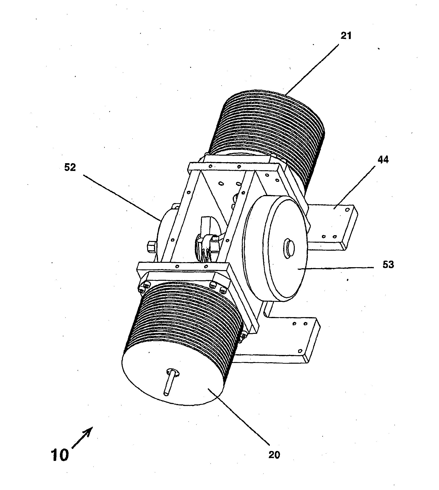
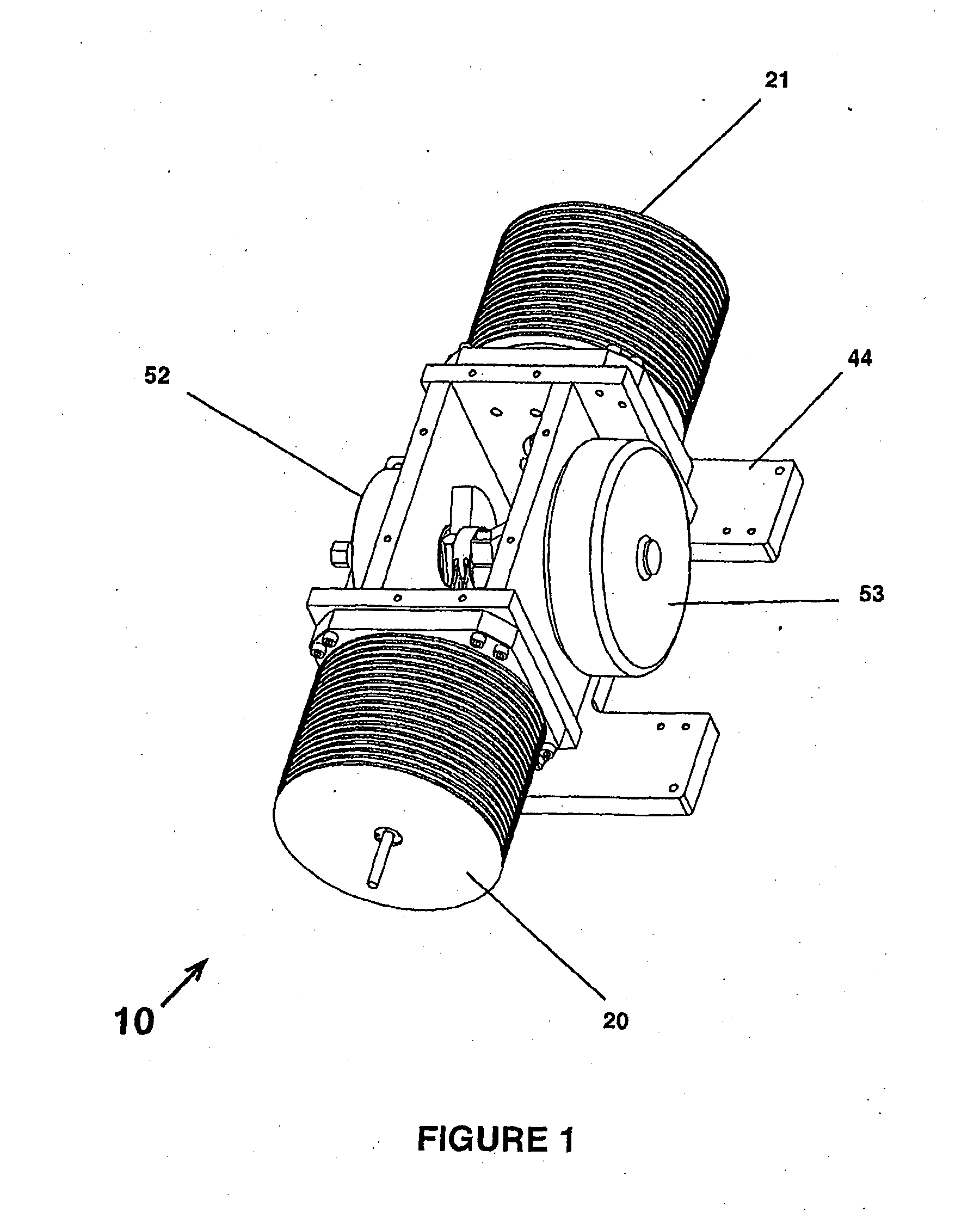
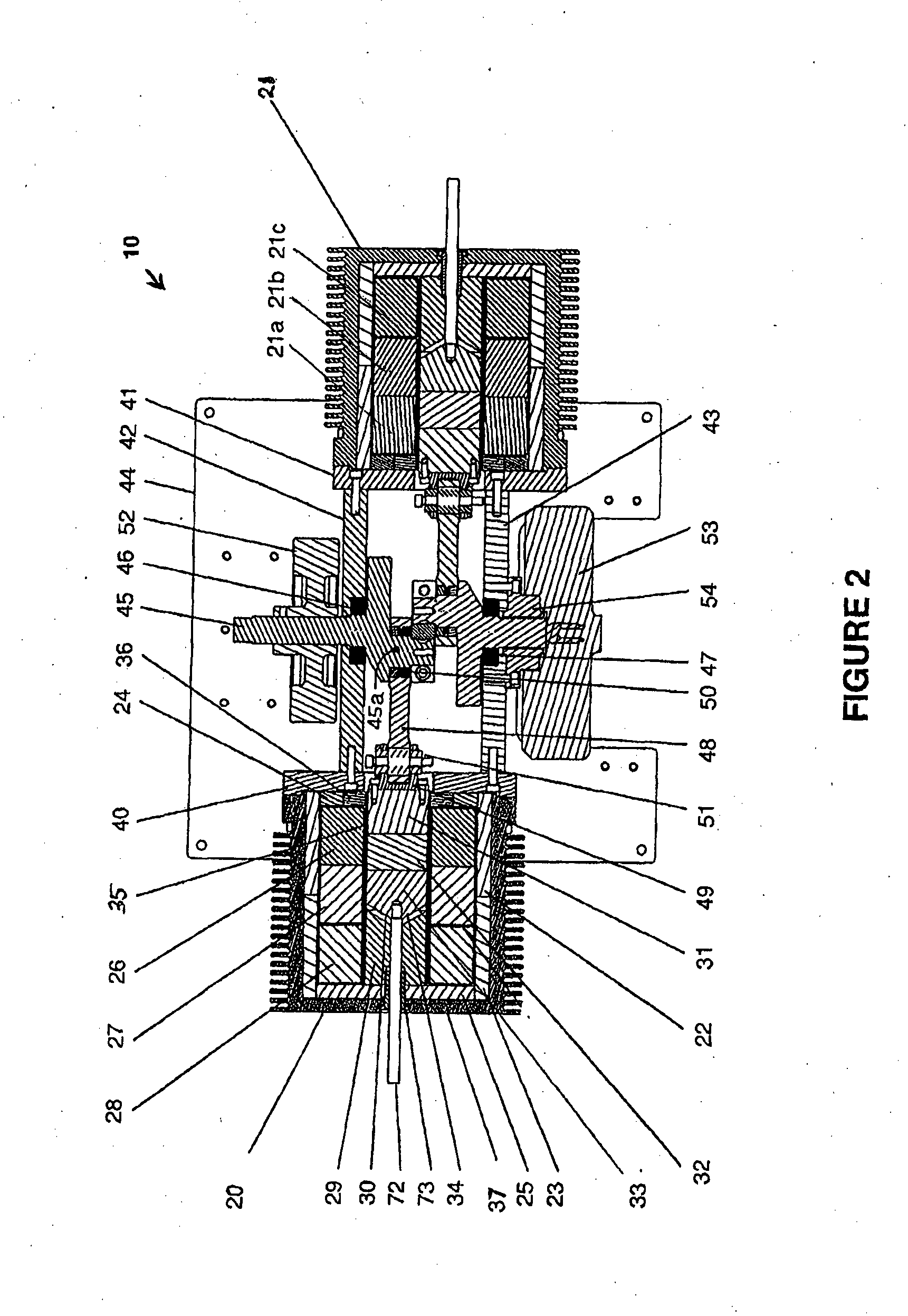
[0106]Referring to FIGS. 1 and 2, solenoid motor 10 includes a pair of solenoid assemblies 20, 21 arranged in an opposing configuration not unlike an IC engine that operates in a “boxer” configuration. Solenoid assembly 20 will be described below in detail. It is to be understood that solenoid assembly 21 may be constructed in similar fashion...


PUM


Abstract

The present application relates to conversion between electrical and mechanical energy. In preferred forms, a solenoid assembly is provided that may include a housing containing a core member and a coil assembly including at least one coil, a plunger assembly adapted for reciprocal movement within said housing between a first position and a second position, and a driver circuit for energizing the coil assembly to cause the plunger assembly to move at least between the first and second positions.

Description

RELATED APPLICATIONS[0001]This application claims priority to Australian Provisional Patent Application No. 2011905005 in the name of E.M.I.P. Pty Ltd, which was filed on 1 Dec. 2011, entitled “Method and Apparatus for Converting Between Electrical and Mechanical Energy” and, Australian Innovation Patent No. 2012101645 in the name of E.M.I.P. Pty Ltd, which was filed on 8 Nov. 2012, entitled “Method and Apparatus for Converting Between Electrical and Mechanical Energy” and, Australian Innovation Patent No. 2012101646 in the name of E.M.I.P. Pty Ltd, which was filed on 8 Nov. 2012, entitled “Method and Apparatus for Converting Between Electrical and Mechanical Energy” and, Australian Innovation Patent No. 2012101648 in the name of E.M.I.P. Pty Ltd, which was filed on 8 Nov. 2012, entitled “Method and Apparatus for Converting Between Electrical and Mechanical Energy” and, Australian Innovation Patent No. 2012101649 in the name of E.M.I.P. Pty Ltd, which was filed on 8 Nov. 2012, entit...

Claims


Application Information

Patent Timeline
Patent Type & Authority Applications(United States)
IPC IPC(8): H01H47/22H02K7/075
CPCH02K33/16H02K16/00H02K7/075F16H21/36H01H47/22H02K7/06F01B29/08H02K33/12
Inventor BELL, TONY
Owner E M I P
Why Eureka
Try Eureka