Key switch device for combined key caps

A technology of key switch and combination key, which is applied in the direction of electric switch, emergency protection device, contact operating mechanism, etc. It can solve the problems of low cost of production equipment, low precision of injection molding, stamping precision, lower limit of elastic force, etc., and achieve the effect of improving production efficiency

Inactive Publication Date: 2018-02-06
陈峰
View PDF4 Cites 3 Cited by
  • Summary
  • Abstract
  • Description
  • Claims
  • Application Information

AI Technical Summary

Problems solved by technology

[0010] Problems existing in the plastic elastic limit structure: plastic elastic limit structures are set on the keycaps, see Figure 3 to Figure 7 . When installing the keycap, first install the keycap sliding part 3 on the upper sliding part of the scissors, and then rotate the keycap downward until the keycap rotating part 2 contacts the upper rotating part 10 of the scissors. During the pressing process, the keycap The two short and thick plastic elastic limit structures of the rotating part 2 need to produce a deformation of about 0.15mm on one side, and enter the matching space of the keycap rotating part 2 after deformation. The width B1 of the two short and thick plastic elastic limit structures is about It is 0.7mm, the length H1 is about 1.6mm, B1 / H1=0.4375, because the plastic is a plastic material, the short and thick plastic elastic limit structure has poor elasticity, low strength, and the limit interference is small. The thinner it is, the two short and thick plastic elastic limit structures (H1 size) of the keycap rotating part 2 limit the design of the low height of the keycap. At the same time, due to the influence of injection molding defects and the two short and thick The mold with plastic elastic limit structure needs oblique drawing structure, etc.
As a result, the two short and thick plastic elastic limit structures of the keycap rotating part 2 have a high defect rate at the factory and during use.
[0011] 1. After the keycaps of the notebook keyboard leave the factory, the problem of the keycap falling off is very prominent. The problem of keydropping is the most prominent and urgent problem of the notebook keyboard at present; the short and thick plastic elastic limit structure of the keycap of the notebook keyboard has been coordinated The margin is 0.15mm on one side. When the fit interference is too small, the key drop phenomenon is likely to occur; when the fit interference is too large, the two short and thick plastic elastic limiters on the keycap rotating part 2 are prone to occur. Hidden dangers of structural fracture failure and buried fracture failure
Two short and thick plastic elastic limit structures have poor elasticity and low strength;
[0012] 2. Thinning the keycap will inevitably shorten it--short and thick plastic elastic limit structure, the short and thick plastic elastic limit structure is shortened, resulting in the lower limit of the elasticity of the short and thick plastic elastic limit structure, which limits the further lower height of the keycap design
[0018] 1. The matching part of the plastic keycap has an undercut structure. The underturn structure of the keycap requires 4 core-pulling mechanisms on the side of the mold. The mold structure is very complicated, resulting in a complex and large mold structure. A pair of molds has 64 keycaps Arrangement design, a total of 64*4 side core-pulling mechanisms;
[0019] 2. Plastic keycaps are affected by injection molding defects, especially the matching parts with small structures, which are prone to injection molding defects;
[0020] 3. The precision of injection molding is lower than the stamping precision of sheet metal, precision injection molding -- the tolerance of small-sized structural injection molded parts is 0.08mm (GB / T14486-2008), linear dimension stamping --- the stamping accuracy of sheet metal is 0.026mm (GB / T 13914- 92), the stamping and bending accuracy of thin plates is 0.5 degrees (GB / T 13915-2002);
[0021] Compared with the sheet metal scissors support, the commonly used plastic scissors support has poor strength, poor stiffness, and poor precision, and there are injection defects in injection molding production, which cannot further reduce the height of the keyboard. The production efficiency of the scissors support is much lower The production efficiency is lower than that of the stepping die (the difference in production efficiency is 92 times - 184 times); although the sheet metal scissor foot support has the advantages of high strength, high rigidity, super high production efficiency, and low production equipment cost, etc.

Method used


Image

  • Key switch device for combined key caps
  • Key switch device for combined key caps
  • Key switch device for combined key caps

Examples


Embodiment 1

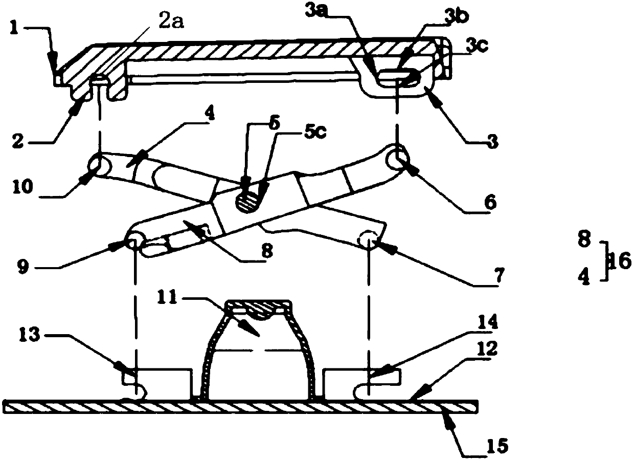
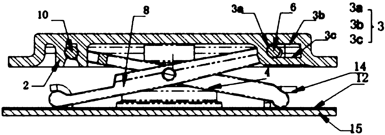
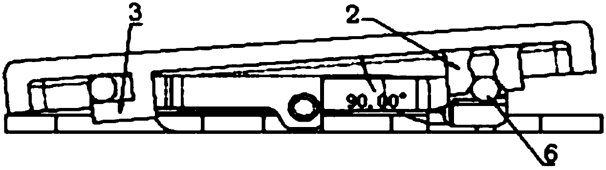
[0105] Embodiment 1, see Figure 17 -- Figure 26 , including a keycap 1 with characters printed on its upper surface, a reset body (consisting of a rubber spring ring 11), a switch circuit (consisting of a membrane switch circuit 12), a support plate 15 with a matching part, and scissor feet with an upper and lower matching part Support 16, the scissor foot support 16 is respectively connected with the keycap 1 and the matching portion of the support plate 15 through the upper and lower matching parts to rotate or slide, and the scissor foot support 16 constitutes a synchronous linkage support structure through the transmission of force between the linkage parts to ensure that the key The cap 1 moves up and down parallel to the support plate. The key cap 1 is composed of the I key assembly 33 and the II key assembly 35. The I key assembly 33 and the II key assembly 35 are fixedly connected, and the I key assembly 33 is located on the II key assembly 35; II The key assembly 3...

Embodiment 2

[0142] Embodiment 2, see Figure 27 , Ⅱ The first bending edge 36 and the second bending edge 37 formed by stamping on the key assembly 35 are bent along the X direction to form the X direction bending part 44; The formed z-direction bending edge 39 and the II bending edge 37 are all along the X direction and point to the middle of the key, and the plate surface is bent near the cantilever end of the II bending edge 37 to form a z-direction bending edge 39, and the key is reversed to match the arc 25 is composed of the upper surface of the bend between the II bending edge 37 and the z-direction bending edge 39, and the undercut fitting part is composed of an arc-shaped key undercut fitting arc 25; in the middle part of the II key assembly 35 Nearby, there is a through hole 35a in the middle of the key II that runs through the board surface; there are key installation guide surfaces 45 formed by chamfering on the outside of the four z-direction bending edges 39; the key underc...

Embodiment 3

[0157] Embodiment 3, see Figure 45 , Ⅱ The mating portion of the key assembly 35 is composed of a first bending portion 49, a second bending portion 50, and a third bending portion 51, wherein the first bending portion 49 and the second bending portion 50 are arranged along the Y direction, and the first bending portion 50 is arranged along the Y direction. The bending part 49 is located between the two second bending parts 50, and the first bending part 49 and the second bending part 50 are provided with a stamped and formed folding arc plate 48 and a guide panel 47; the first bending part 49 of the folded arc plate 48 corresponds to the position of the folded arc plate 48 of the second bending portion 50 and has the same center, and the folded arc plate 48 of the same circle center constitutes the keycap rotating portion 2, and the guide panel of the first bent portion 49 47. The position of the guide panel 47 of the second bending part 50 corresponds to an inverted eight ...


PUM


Abstract

The invention relates to a key switch device for combined key caps. The key switch device comprises the key caps with characters, a reset body, a switch loop, a supporting board with a matching portion and scissors foot supports with upper and lower matching portions, wherein the scissors foot supports are in rotatable or sliding connection with the key caps and the supporting board through the upper and lower matching portions, force transmission between the scissors foot supports is carried out to form a synchronization linkage supporting structure to guarantee that the key caps do up and down lifting motion in a mode of be parallel with the supporting board, a matching portion of the key cap 1 comprises a key cap supporting matching portion, a buckle matching portion and a key cap anti-loosening portion, the key cap I comprises a key assembly I 33 and a key assembly II 35, the key assembly I 33 is fixedly connected with the key assembly II 35, the key assembly I 33 is arranged abovethe key assembly II 35, the key assembly II 35 is formed through stamping forming of a metal plate, the matching portion of the key cap 1 is arranged above the key assembly II 35, and a character isarranged above the key assembly I 33.

Description

[0001] Priority Statement: [0002] Claim 1 to claim 6 and claim 10 of the present invention, claiming the priority of the corresponding embodiment of the claim of the patent application for invention with the application number 2016108644627 submitted to the China National Intellectual Property Office on September 30, 2016; [0003] Claims 1 to 10 of the present invention require the priority of the invention patent application No. 2017103083067 submitted to the China National Intellectual Property Office on May 04, 2017, and the corresponding embodiments. technical field [0004] The present invention relates to a key switch device for performing keystroke operations, and more particularly to a key switch device incorporated in a keyboard as an input device of an electronic device. The invention also relates to a keyboard provided with a plurality of such key switch devices. Background technique [0005] see figure 1 , figure 2 The key structure device of existing keyb...

Claims


Application Information

Patent Timeline
Patent Type & Authority Applications(China)
IPC IPC(8): H01H13/14H01H13/20H01H3/12H01H11/00
CPCH01H13/14H01H3/125H01H11/00H01H13/20H01H2227/036
Inventor 陈峰
Owner 陈峰
Why Eureka
Try Eureka