
Metal U-shaped pressing wire vertical machine structure

A wire-pressing and U-shaped technology, applied in the field of metal U-shaped wire-pressing vertical device structure, can solve the problems of inconvenient adjustment of wire pressing force, wire wear, poor wire guiding and positioning effect, etc. Small friction, improved coding effect

Inactive Publication Date: 2018-02-09
周文文
View PDF0 Cites 0 Cited by
  • Summary
  • Abstract
  • Description
  • Claims
  • Application Information

AI Technical Summary

Problems solved by technology

[0005] In order to solve the above-mentioned technical problems, the present invention provides a metal U-shaped crimping straightener structure to solve the problem that the existing crimping straightener structure has a poor guiding and positioning effect on the electric wires, and it is inconvenient to adjust the strength of the electric wires, and the electric wires are sliding. The problem of serious wear and tear during the cutting process

Method used


Image

  • Metal U-shaped pressing wire vertical machine structure
  • Metal U-shaped pressing wire vertical machine structure
  • Metal U-shaped pressing wire vertical machine structure

Examples


Embodiment

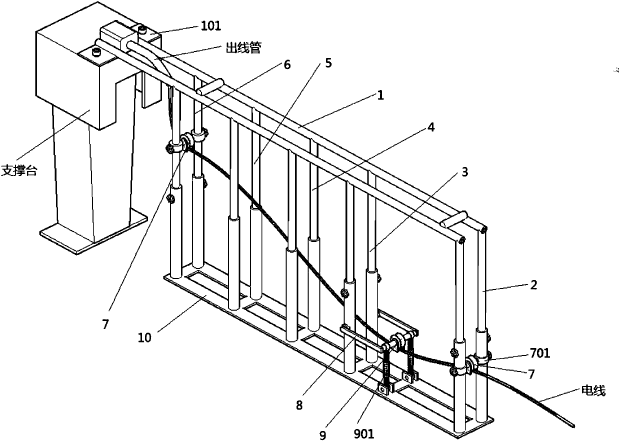
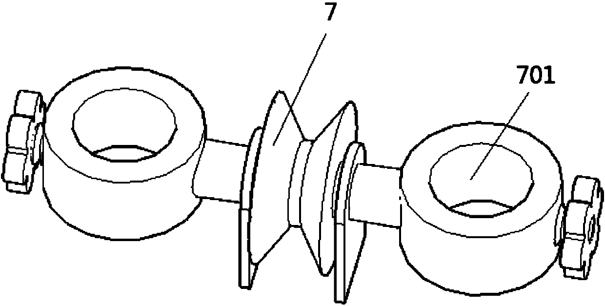
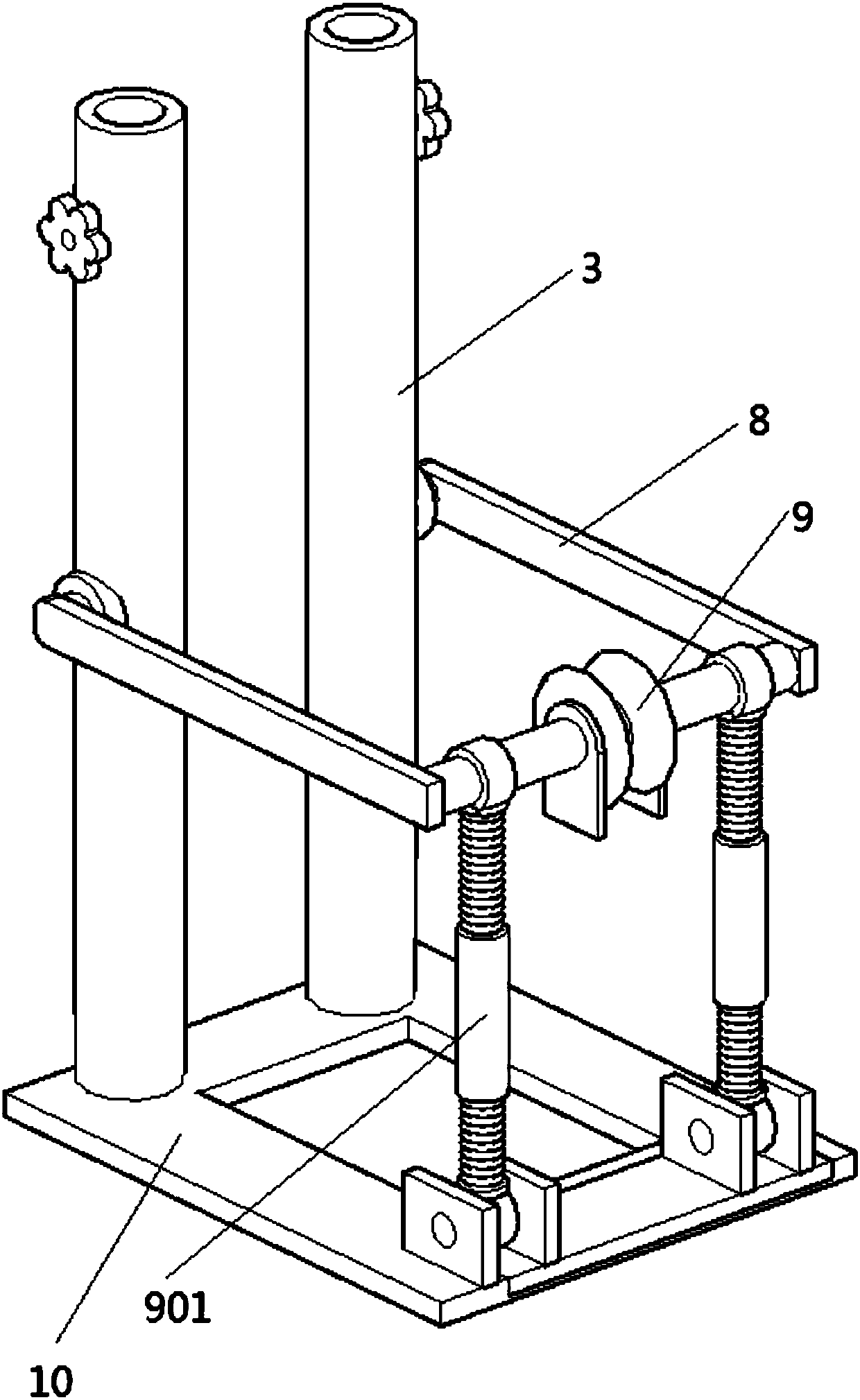
[0023] as attached figure 1 to attach image 3 Shown:

[0024] The present invention provides a metal U-shaped crimping vertical device structure, including a support bar 1, a fixed plate 101, a first support bar 2, a second support bar 3, a third support bar 4, a fourth support bar 5, and a fourth support bar Rod 6, pulley 7, pulley sliding sleeve 701, rotating support rod 8, second pulley 9, double-headed adjusting bolt 901 and base plate 10, the top of the base plate 10 is supported and welded with the first support rod 2 sequentially from left to right, The second support 3, the third support rod 4, the fourth support rod 5 and the fourth support rod 6, wherein the second support 3, the third support rod 4, the fourth support rod 5 and the fourth support rod 6 are equidistantly arranged , the distance between the first support rod 2 and the second support 3 is longer than the distance between the other four support rods; the top end surface of the bottom plate 10 between...


PUM


Abstract

The invention provides a metal U-shaped crimping vertical device structure, which includes a second pulley, a double-headed adjusting bolt and a bottom plate. The support cross bar is provided with two support bars that are symmetrically supported on the left and right and five support bars that are arranged in pairs. , and the two supporting bars are connected and fixed together by two connecting bars at the front and back; the right ends of the two supporting bars are symmetrically welded with two fixing plates extending outward, and the centers of the two fixing plates A through hole is provided through each of them, and two hexagon socket screws pass through the above two through holes, and the two support cross bars are locked and fixed on the support platform. For the setting of the second pulley of the present invention, the central positioning shafts of the pulley and the second pulley are symmetrically welded and fixed with two clamping plates vertically downward, and these two clamping plates are close to the left and right sides of the pulley and the second pulley , The two clamping plates can play a position-limiting role, effectively preventing the wire from tripping out from the inside of the circular clamping groove of the three pulleys, causing the equipment to be stuck.

Description

technical field [0001] The invention belongs to the technical field of crimping straighteners, in particular to a metal U-shaped crimping straightener structure. Background technique [0002] In the process of fully automatic cutting line, there are always unclear codes, knotted wires, and equipment failures caused by equipment jamming, and then a metal U-shaped crimping vertical device structure is needed to ensure that the wires remain tight during transmission. state, to avoid tangled wires. [0003] Based on the above, the inventors found that the existing crimping straighteners have poor guiding and positioning effects on the wires, inconvenient adjustment of the force of pressing the wires, and serious wear and tear of the wires during the sliding cutting process. [0004] Therefore, in view of this, researches and improvements are made on the existing structure and defects, and a metal U-shaped crimping vertical device structure is provided, in order to achieve the p...

Claims


Application Information

Patent Timeline
IPC IPC(8): B21F23/00
CPCB21F23/00
Inventor 周文文张奎朱丹丹郭红波郭雷王德刚
Owner 周文文
Learn More