
Steelyard type solar wing 360 degree zero-gravity unfolding system

A deployment system and zero-gravity technology, applied in the field of solar wing deployment, can solve problems such as the inability to adapt to zero-gravity deployment of solar wings, and achieve the effect of ingenious design and simple structure

Pending Publication Date: 2018-02-09
TIANJIN AEROSPACE ELECTROMECHANICAL EQUIP RES INST
View PDF0 Cites 4 Cited by
  • Summary
  • Abstract
  • Description
  • Claims
  • Application Information

AI Technical Summary

Problems solved by technology

At present, the solar wing deployment of spacecraft is mostly two-dimensional straight line deployment or arc trajectory deployment within a certain angle. The zero-gravity ground simulation technology for these two solar wing deployments is relatively mature, but there are great differences in trajectory and range. Limitations, unable to adapt to the 360° zero-gravity deployment of the solar wing

Method used


Image

  • Steelyard type solar wing 360 degree zero-gravity unfolding system
  • Steelyard type solar wing 360 degree zero-gravity unfolding system
  • Steelyard type solar wing 360 degree zero-gravity unfolding system

Examples


Embodiment Construction

[0024] It should be noted that, in the case of no conflict, the embodiments of the present invention and the features in the embodiments can be combined with each other.

[0025] In describing the present invention, it should be understood that the terms "center", "longitudinal", "transverse", "upper", "lower", "front", "rear", "left", "right", The orientations or positional relationships indicated by "vertical", "horizontal", "top", "bottom", "inner", "outer", etc. are based on the orientation or positional relationships shown in the drawings, and are only for the convenience of describing the present invention Creation and simplification of description, rather than indicating or implying that the device or element referred to must have a specific orientation, be constructed and operate in a specific orientation, and therefore should not be construed as limiting the invention. In addition, the terms "first", "second", etc. are used for descriptive purposes only, and should no...


PUM


Abstract

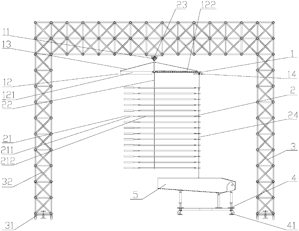
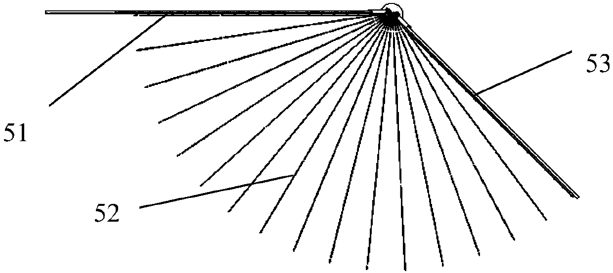
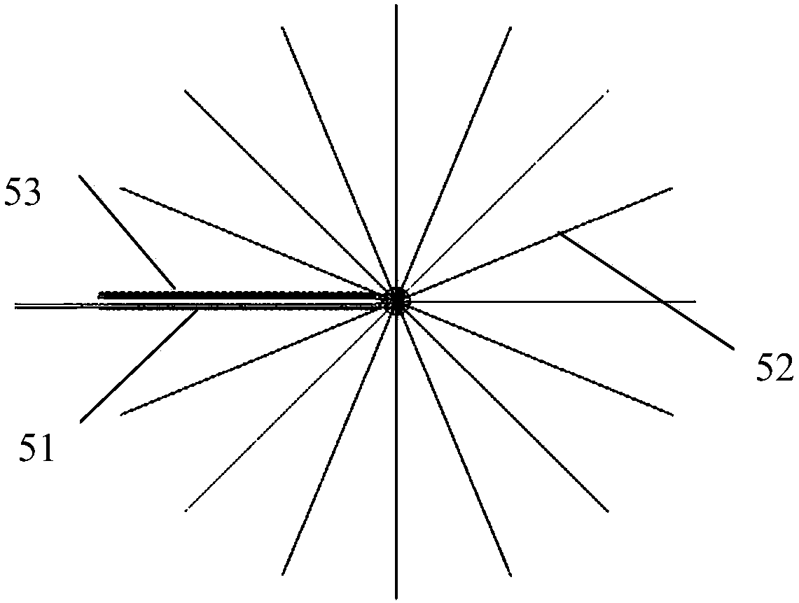
The invention provides a steelyard type solar wing 360 degree zero-gravity unfolding system. The steelyard type solar wing 360 degree zero-gravity unfolding system comprises an unfolding frame, a rotational balancing frame and a steelyard assembly, wherein the rotational balancing frame is mounted at the top of the unfolding frame, and comprises a rotating mechanism and a balance beam; the rotating mechanism is fixed on the unfolding frame; the balance beam is fixed to the lower end of the rotating mechanism; the load end of the balance beam is connected with a movable boxboard of a solar wing; the steelyard assembly is arranged below the rotating mechanism, and fixed on the unfolding frame; and load ends of the steelyard assembly are respectively connected with unfolding ribs of the solarwing. According to the steelyard type solar wing 360 degree zero-gravity unfolding system provided by the invention, the unfolding frame, the rotational balancing frame, the steelyard assembly and afixed support can make gravity compensation for the solar wing of a spacecraft when an unfolding test is performed on the ground, so that 360 degree zero-gravity unfolding is realized.

Description

technical field [0001] The invention belongs to the technical field of solar wing deployment, and in particular relates to a steelyard solar wing 360° zero-gravity deployment system. Background technique [0002] When the solar wing of the spacecraft is deployed on the ground, in order to truly simulate the state of space deployment, gravity compensation needs to be performed during the ground test to achieve zero-gravity deployment. At present, the solar wing deployment of spacecraft is mostly two-dimensional straight line deployment or arc trajectory deployment within a certain angle. The zero-gravity ground simulation technology for these two solar wing deployments is relatively mature, but there are great differences in trajectory and range. Limitations, unable to adapt to the 360° zero-gravity deployment of the solar wing. Contents of the invention [0003] In view of this, the present invention aims to propose a steelyard solar wing 360° zero-gravity deployment syst...

Claims


Application Information

Patent Timeline
Patent Type & Authority Applications(China)
IPC IPC(8): B64G7/00
CPCB64G7/00
Inventor 左祥赟李瑞贤张玉美吴霞
Owner TIANJIN AEROSPACE ELECTROMECHANICAL EQUIP RES INST
Learn More