Electromagnetic Actuator

An electromagnetic actuator and electromagnetic field technology, applied in the direction of circuits, magnets, magnetic objects, etc., can solve the problems of reduced response of moving output pins, increased sliding resistance, etc.

Inactive Publication Date: 2018-02-09
DENSO CORP
View PDF5 Cites 3 Cited by
  • Summary
  • Abstract
  • Description
  • Claims
  • Application Information

AI Technical Summary

Problems solved by technology

As a result, the sliding resistance between the output pin and the gui...

Method used


Image

  • Electromagnetic Actuator
  • Electromagnetic Actuator
  • Electromagnetic Actuator

Examples


no. 1 approach

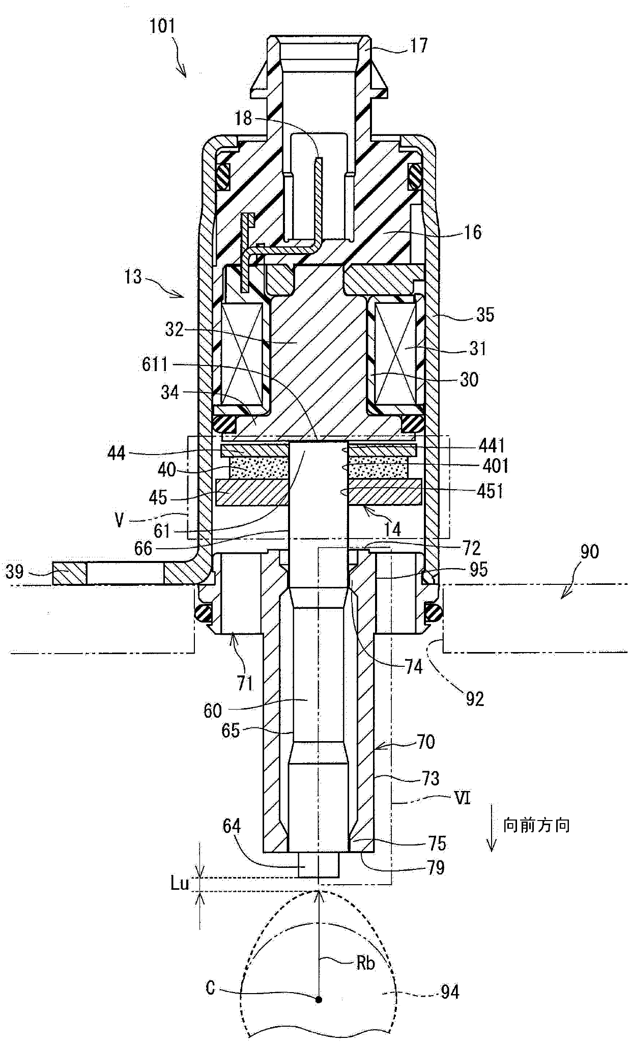
[0044] will refer to Figure 3 to Figure 10 The structure of the actuator 101 will be described.

[0045] Such as image 3 and Figure 4 As shown, the actuator 101 is composed of a stationary unit 13 and a movable unit 14 .

[0046] The stationary unit 13 is fixed on the engine head 90 and is composed of a coil 31 , a stator 32 , a yoke 35 and a guide member 70 .

[0047] In the coil 31 , a winding is wound around the outer circumference of the bobbin 30 . The bobbin 30 is made of resin and fitted to the stator 32 . The bobbin 30 insulates the winding of the coil 31 from the stator 32 .

[0048] The resin molding unit 16 is provided on the rear side of the bobbin 30 of the coil 31 , that is, on the side opposite to the movable unit 14 . The connector 17 is integrally formed with the resin molding unit 16 .

[0049] When power is supplied to the coil 31 from an external power source (not shown) via the terminal 18 of the connector 17 , the coil 31 generates a magnetic fi...

no. 2 approach

[0133] The electromagnetic actuator 102 of the second embodiment differs from the actuator 101 of the first embodiment in the position of the first support portion and the position of the radially inward recessed portion.

[0134] Such as Figure 11 As shown, when the output pin 60 is in its initial state, the first radially inner corner 742 of the first support portion 74 is located therein axially separated from the rear radially outer corner 653 of the output pin 60 in the rearward direction toward the output pin 60 The rear end 61 position. The same advantages as those of the first embodiment can also be obtained in the second embodiment.

no. 3 approach

[0136] The electromagnetic actuator 103 of the third embodiment differs from the actuator 101 of the first embodiment in the structure of the stationary unit and the structure of the movable unit.

[0137] Such as Figure 12 As shown, the actuator 103 of this embodiment has a stationary unit 113 and a movable unit 114 .

[0138] The movable unit 114 has an output pin 160 and an armature 180 .

[0139] The armature 180 is made of a magnetic material, and has a connection portion 181 on the front side and a flange portion 182 (magnet opposing portion 182 ) on the rear side. The armature 180 is movable together with the output pin 160 in the axial direction.

[0140] The main part of the armature 180 is located in the radially inner space of the coil 131 .

[0141] The connection part 181 has a connection hole 183 extending in the axial direction and having a bottom end. The rear end 61 of the output pin 160 is inserted into the connection hole 183 so that the output pin 160 ...


PUM


Abstract

An electromagnetic actuator (101) is composed of a movable unit (14) and a stationary unit (13). The movable unit (14) has an output pin (60) movably supported by a guide member (70). The guide member(70) has a cylindrical portion (73) and a first support portion (74) and a second support portion (74) which are formed on an inner peripheral surface of the cylindrical portion (73). A radially inwardly recessed portion (65) is formed on an outer peripheral surface of the output pin (60). Straight portions (66, 68) are formed in the output pin at both axial sides of the radially inwardly recessed portion, wherein an outer diameter of the straight portion is larger than an outer diameter of the radially inwardly recessed portion (65). Each of the straight portions of the output pin (60) is movably in contact with the first and second support portions (74, 75).

Description

technical field [0001] The present disclosure relates to an electromagnetic actuator for driving its output pin by electromagnetic force. Background technique [0002] Electromagnetic actuators are known in the art, eg as disclosed in EP 1,913,605 B1, according to which a movable unit with permanent magnets is moved by electromagnetic force generated by a coil to drive an output pin. In the prior art electromagnetic actuator, a constricted portion (small diameter portion) is formed on the outer periphery of the output pin, and straight portions (large diameter portions) on both axial sides of the constricted portion of the output pin are movable by guide members. Supported so that the output pin is movable in the axial direction. [0003] In the prior art described above, by expanding the radial gap between the output pin and the guide member by utilizing the constricted portion formed in the output pin, the viscous resistance of oil flowing into the radial gap is reduced. ...

Claims


Application Information

Patent Timeline
IPC IPC(8): F01L13/00
CPCF01L13/0015F01L13/0036F01L2013/0052F01L2013/101F01L2810/02F01L2301/00H01F7/121H01F7/1646H01F2007/1692
Inventor 天野均
Owner DENSO CORP
Why Eureka
Try Eureka