
A cantilever beam and photoacoustic cell double resonance enhanced photoacoustic spectroscopy detection system and method

A technology of photoacoustic spectroscopy and detection system, which is used in measurement devices, material analysis by optical means, instruments, etc., can solve the problems of limited photoacoustic signal enhancement effect and large 1/f noise, and achieve enhanced photoacoustic signal amplitude. , High sensitivity trace gas detection, enhance the effect of photoacoustic signal

Active Publication Date: 2020-08-14
DALIAN UNIV OF TECH
View PDF4 Cites 0 Cited by
  • Summary
  • Abstract
  • Description
  • Claims
  • Application Information

AI Technical Summary

Problems solved by technology

[0004] The purpose of the present invention is to propose a cantilever beam and photoacoustic cell dual-resonance enhanced photoacoustic spectrum detection system and method, aiming to solve the problems of limited photoacoustic signal enhancement effect and large 1 / f noise in the traditional CEPAS measurement method To further improve the gas detection sensitivity of the CEPAS system, and expand a larger space for the application of photoacoustic spectroscopy in trace gas detection

Method used


Image

  • A cantilever beam and photoacoustic cell double resonance enhanced photoacoustic spectroscopy detection system and method
  • A cantilever beam and photoacoustic cell double resonance enhanced photoacoustic spectroscopy detection system and method
  • A cantilever beam and photoacoustic cell double resonance enhanced photoacoustic spectroscopy detection system and method

Examples


Embodiment Construction

[0020] The specific embodiments of the present invention will be described in detail below in conjunction with the technical solutions and accompanying drawings.

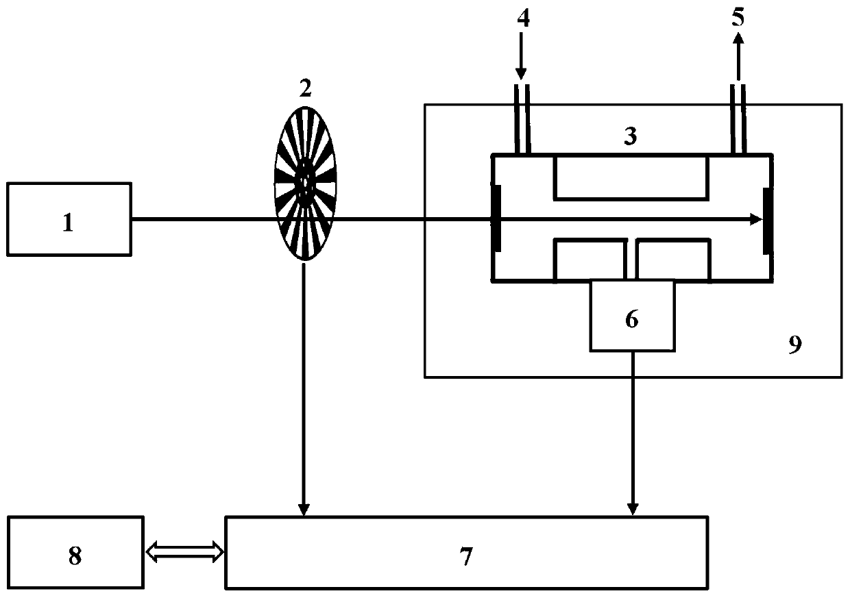
[0021] A dual-resonance enhanced photoacoustic spectrum detection system of a cantilever beam and a photoacoustic cell, mainly including a light source 1, an optical modulator 2, a resonant photoacoustic cell 3, an air inlet 4, an air outlet 5, a cantilever beam microphone 6, and a lock Phase amplifier 7, computer 8 and incubator 9.

[0022] By setting the temperature of the incubator 9, the resonant frequency of the resonant photoacoustic cell 3 is fine-tuned, so that the resonant frequency of the resonant photoacoustic cell 3 and the cantilever beam microphone 6 can be precisely matched; the light source 1 is intensity-modulated by the light modulator 2 After entering the resonant photoacoustic cell 3; the gas to be measured enters the resonant photoacoustic cell 3 from the air inlet 4 and is discharged from the g...


PUM

PropertyMeasurementUnit
Resonant frequencyaaaaaaaaaa
lengthaaaaaaaaaa
lengthaaaaaaaaaa

Abstract

The invention discloses a cantilever beam and photoacoustic cell double-resonance enhanced-type photoacoustic spectrum detection system and a method, and belongs to the technical field of trace gas detection. According to the cantilever beam and photoacoustic cell double-resonance enhanced-type photoacoustic spectrum detection system and the method, sound wave generated by excitation of gas molecules with a light source is subjected to coherence stack in an acoustic resonance tube of a resonant photoacoustic cell, so that photoacoubtic signal amplitude is increased effectively; at the same time, fine adjustment on the photoacoustic cell resonant frequency is realized through precise design and temperature control of a cantilever beam structure, so that accurate matching of the cantilever beam resonant frequency with the photoacoustic cell resonant frequency is realized, and the photoacoubtic signals are enhanced further via one step resonant of the cantilever beam; the double-resonanceenhanced-type photoacoustic spectrum method is combined with a phase-locked amplifier to realize super sensitive gas detection. The double-resonance enhancing effect of the cantilever beam and the photoacoustic cell is capable of realizing obvious amplification of photoacoubtic signals, the system working frequency is controlled at kHz order of magnitude, 1 / f noise is reduced greatly, and a technological scheme with competitiveness is provided for super low concentration gas detection.

Description

technical field [0001] The invention belongs to the technical field of trace gas detection, and relates to a dual-resonance enhanced photoacoustic spectrum detection system and method of a cantilever beam and a photoacoustic cell. Background technique [0002] Photoacoustic gas sensors have been widely used in the fields of dissolved gas analysis in transformer oil, environmental pollution gas monitoring, and flammable and explosive gas monitoring in coal mines due to their significant advantages such as high sensitivity and small sampling volume. [0003] In traditional photoacoustic spectroscopy detection, gas molecules absorb light energy and undergo non-radiative transitions to generate sound waves, which are usually converted into electrical signals by an electret microphone. According to the principle of photoacoustic spectroscopy, the sensitivity of photoacoustic measurements is proportional to the sensitivity of the acoustic wave detector. Compared with condenser mi...

Claims


Application Information

Patent Timeline
Patent Type & Authority Patents(China)
IPC IPC(8): G01N21/17G01N21/01
CPCG01N21/01G01N21/1702G01N2021/1704
Inventor 陈珂于清旭宫振峰郭珉周新磊
Owner DALIAN UNIV OF TECH
Learn More