SRAM type FPGA turnover fault injection device and fault injection method

A fault injection and device technology, applied in fault hardware testing methods, detecting faulty computer hardware, instruments, etc., can solve the problems of low reliability of test results, unreal fault models, and complex equipment, and achieve test results. Real and reliable, low cost, flexible configuration effect

Active Publication Date: 2018-02-09
湖南斯北图科技有限公司
View PDF4 Cites 12 Cited by
  • Summary
  • Abstract
  • Description
  • Claims
  • Application Information

AI Technical Summary

Problems solved by technology

[0005] Aiming at the problem, the present invention proposes a SRAM type FPGA flipping fault injector and a fault injection method, which can overcome the complexity and high cost of existing hardware fault injection equipment, and the fault model of existing software fault injection is not realistic enough to cause injection Disadvantages such as low reliability of post-test results

Method used


Image

  • SRAM type FPGA turnover fault injection device and fault injection method
  • SRAM type FPGA turnover fault injection device and fault injection method
  • SRAM type FPGA turnover fault injection device and fault injection method

Examples


Embodiment 1

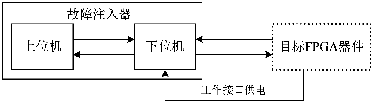
[0045] This embodiment provides a kind of SRAM type FPGA flipping fault injector, its structure is as follows figure 1 As shown, the fault injector includes:

[0046] Upper computer, lower computer. The lower computer is provided with a working interface, and the working interface communicates with the fault injection interface of the target FPGA device. The upper computer and the lower computer communicate through the Ethernet protocol, such as UDP protocol, TCP protocol and other communications.

[0047] The upper computer is used for parameter setting, configuration bit stream generation, and instruction sending; the lower computer is responsible for performing related operations. The upper computer sends a device identification request command, and determines the corresponding device model according to the target FPGA device ID fed back by the lower computer; and instructs the lower computer to implement fault injection on the target FPGA device through the fault injection...

Embodiment 2

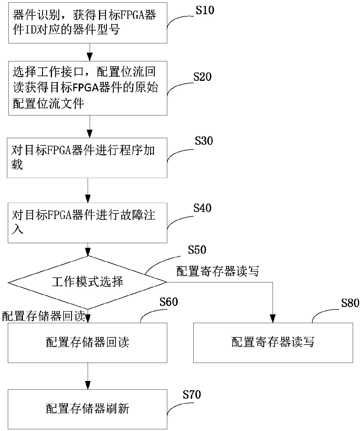
[0142] Embodiment 2 of the present invention also provides a SRAM type FPGA flipping fault injection method, the specific implementation process of which is the same as that of the fault injector in Embodiment 1, and will not be described in detail here.

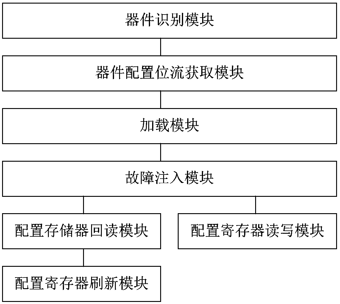
[0143] In the second embodiment above, step S60-step S70 may not be included. In this case, the fault injection method lacks the function of reading back and refreshing the configuration memory of the target FPGA device.

[0144] Step S80 may also not be included in the second embodiment above. In this case, the fault injection method lacks the function of reading and writing configuration registers of the target FPGA device.


PUM


Abstract

The invention provides an SRAM type FPGA turnover fault injection device and fault injection method. An upper computer indicates a lower computer to perform chain device identification, thereby obtaining a device type corresponding to an ID of a target FPGA device; the upper computer selects a working interface and indicates the lower computer to perform configuration bit stream backward reading through the working interface; an original configuration bit stream file of the target FPGA device is obtained; the upper computer indicates the lower computer to finish power-on program loading of thetarget FPGA device by utilizing the original configuration bit stream file of the target FPGA device; the upper computer generates a turnover fault injection bit stream file according to a fault injection type; and the lower computer is indicated to finish fault injection for the target FPGA device through the selected working interface by utilizing the fault injection bit stream file. The shortcomings that an existing hardware fault injection device is complex and high in cost, a test result after injection is low in credibility because an existing fault model for software fault injection isinsufficiently real, and the like can be overcome.

Description

technical field [0001] The present invention relates, in particular, to a SRAM (Static RAM, Static Random Access Memory) type FPGA (Field Programmable Gate Array, Field Programmable Gate Array) flip fault injector and a fault injection method. Background technique [0002] Single event effects mainly include SEU (Single Event Upset, single event flip), SET (Single Event Transient, single event transient pulse), SEL (Single Event Latch, single event lock), etc., among which SEU is the most important form of expression. For the SRAM type FPGA, due to the SRAM process it adopts, it is very prone to single-event effect failures, especially single-event upset failures. From the perspective of the proportion of single event upset faults, configuration memory accounts for the largest proportion, followed by LUT-type RAM, block RAM and flip-flops, and other (such as SET, SEFI) single event effect faults account for a small proportion , the SEU of the configuration memory is the mos...

Claims


Application Information

Patent Timeline
Patent Type & Authority Applications(China)
IPC IPC(8): G06F11/22G06F11/263G06F11/00
CPCG06F11/008G06F11/2273G06F11/263
Inventor 杨艳
Owner 湖南斯北图科技有限公司
Why Eureka
Try Eureka