

Overvoltage protection circuit and switching power supply
An overvoltage protection circuit and circuit technology, applied in emergency protection circuit devices, electrical components and other directions, can solve the problems of affecting the service life, component damage of switching power supply, unstable mains voltage, etc., to achieve overvoltage protection, The effect of preventing damage
- Summary
- Abstract
- Description
- Claims
- Application Information
AI Technical Summary
Problems solved by technology
Method used
Image

Examples
Embodiment 1
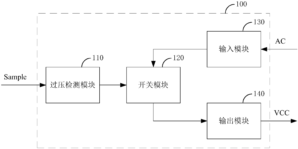
[0047] figure 1 The structure of an overvoltage protection circuit 100 provided by an embodiment of the present invention is shown. For the convenience of description, only the parts related to the embodiment of the present invention are shown, and the details are as follows:
[0048] Such as figure 1 As shown, an overvoltage protection circuit 100 provided by an embodiment of the present invention includes an overvoltage detection module 110 , a switch module 120 , an input module 130 and an output module 140 .
[0049] The output terminal of the overvoltage detection module 110 is connected to the controlled terminal of the switch module 120 , the output terminal of the input module 130 is connected to the input terminal of the switch module 120 , and the output terminal of the switch module 120 is connected to the input terminal of the output module 140 .
[0050] The input terminal of the overvoltage detection module 110 receives an external sampling signal Sample, and th...
Embodiment 2
[0061] Embodiment 2 is a further refinement of the structure of the overvoltage protection circuit 100 provided in Embodiment 1.
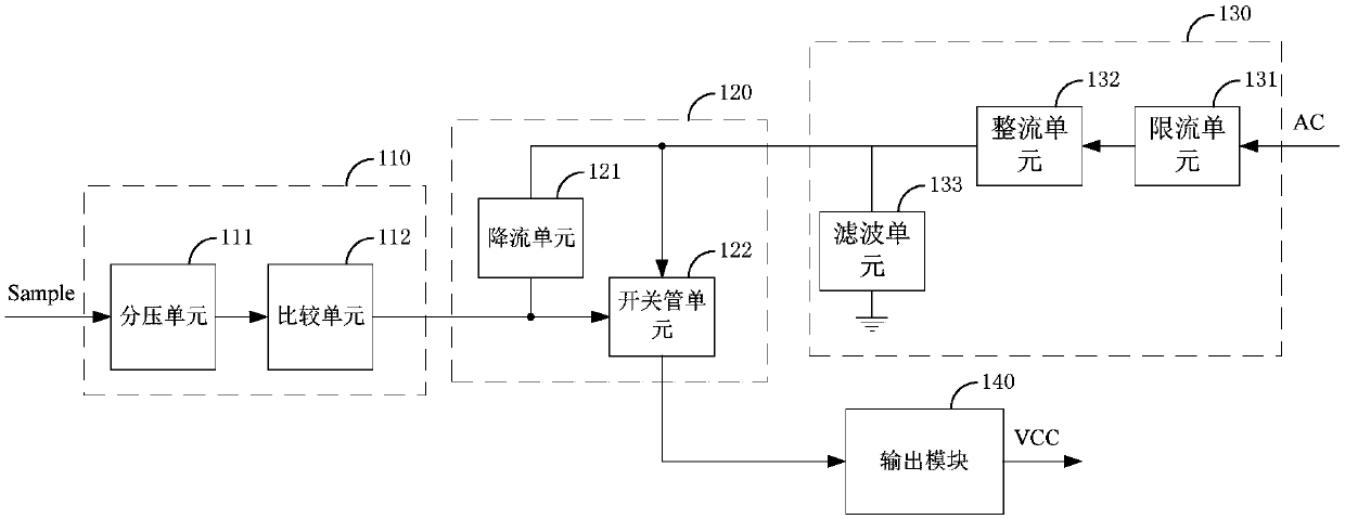
[0062] Such as figure 2 As shown, in one embodiment of the present invention, figure 1 The overvoltage detection module 110 includes a voltage division unit 111 and a comparison unit 112 .
[0063] The input terminal of the voltage dividing unit 111 is the input terminal of the overvoltage detection module 110 , the output terminal of the voltage dividing unit 111 is connected to the input terminal of the comparison unit 112 , and the output terminal of the comparison unit 112 is the output terminal of the overvoltage detection module 110 .
[0064] The voltage dividing unit 111 receives the sampling signal Sample for voltage dividing processing and then outputs the down-voltage sampling signal to the comparison unit 112 , and the comparison unit 112 controls the switch module 120 to be in an off state or an on-state according to the voltage of t...
Embodiment 3
[0073] Embodiment 3 is a further refinement of the structure of the overvoltage protection circuit 100 provided in Embodiment 2.
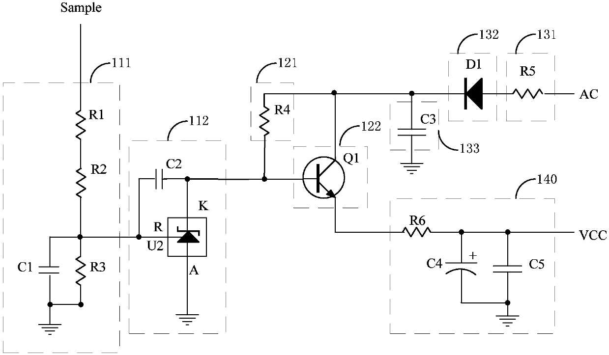
[0074] Such as image 3 As shown, in one embodiment of the present invention, figure 2 The voltage dividing unit 111 includes a first resistor R1, a second resistor R2, a third resistor R3 and a first capacitor C1.
[0075] The first end of the first resistor R1 is the input end of the voltage dividing unit 111, the second end of the first resistor R1 is connected to the first end of the second resistor R2, and the second end of the second resistor R2 is connected to the first end of the third resistor R3. One terminal is commonly connected with the first terminal of the first capacitor C1 to form the output terminal of the voltage dividing unit 111 , and the second terminal of the third resistor R3 is commonly connected with the second terminal of the first capacitor C1 to the ground.
[0076] In this embodiment, the voltage dividing unit 111 c...
PUM
 Abstract
Description
Claims
Application Information