Display device

A technology for display devices and indicator lights, applied in electromagnetic transceivers, signal transmission systems, instruments, etc., can solve problems such as high cost, affect user experience, and reduce the aesthetics of display devices, achieve small size, reduce width, and reduce cost effect

Active Publication Date: 2018-02-09
SHENZHEN SKYWORTH RGB ELECTRONICS CO LTD
View PDF5 Cites 4 Cited by
  • Summary
  • Abstract
  • Description
  • Claims
  • Application Information

AI Technical Summary

Problems solved by technology

[0003] In the existing display device, the signal receiver and the indicator light are arranged on a separate PCB board and installed at the bottom of the display device, which not only has high cost, but also affects the width of the lower frame of the display device, thereby reducing the appearance of the display device degree, affecting user experience

Method used


Image

  • Display device
  • Display device
  • Display device

Examples


Embodiment 1

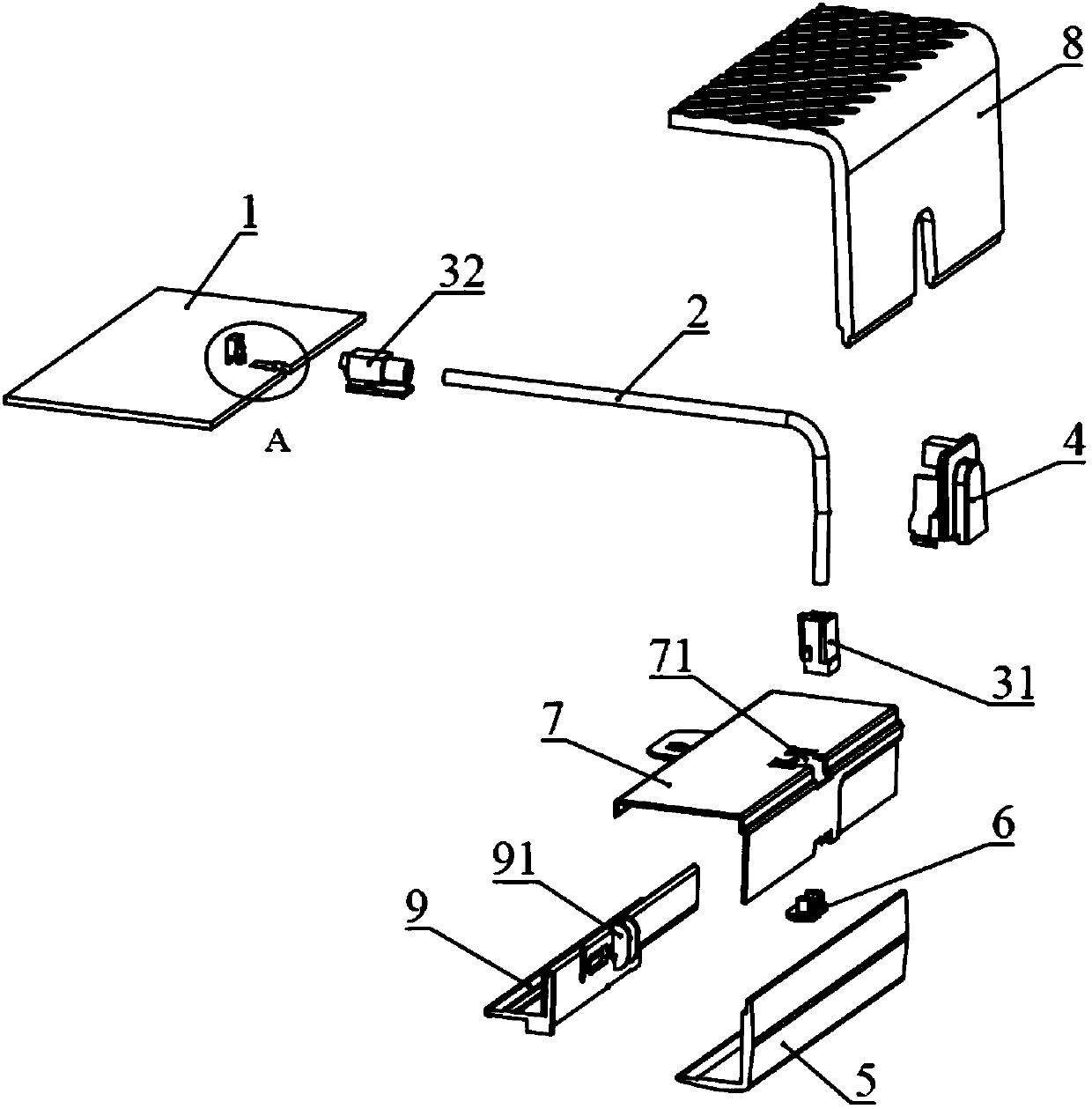
[0042] Such as Figure 1-Figure 14 As shown, the present embodiment provides a display device, which can be a TV, a monitor, etc., and includes a front case 5 and a rear case 8, the front case 5 and the rear case 8 enclose the outer casing of the display device, and the space in the casing It is provided with a backlight module, a display screen and a main board PCB1.

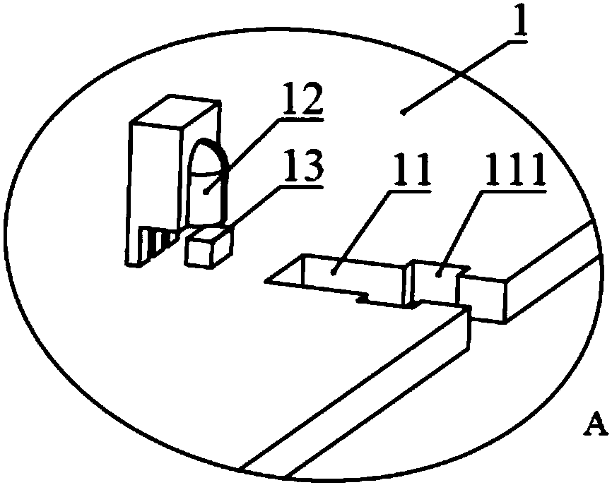
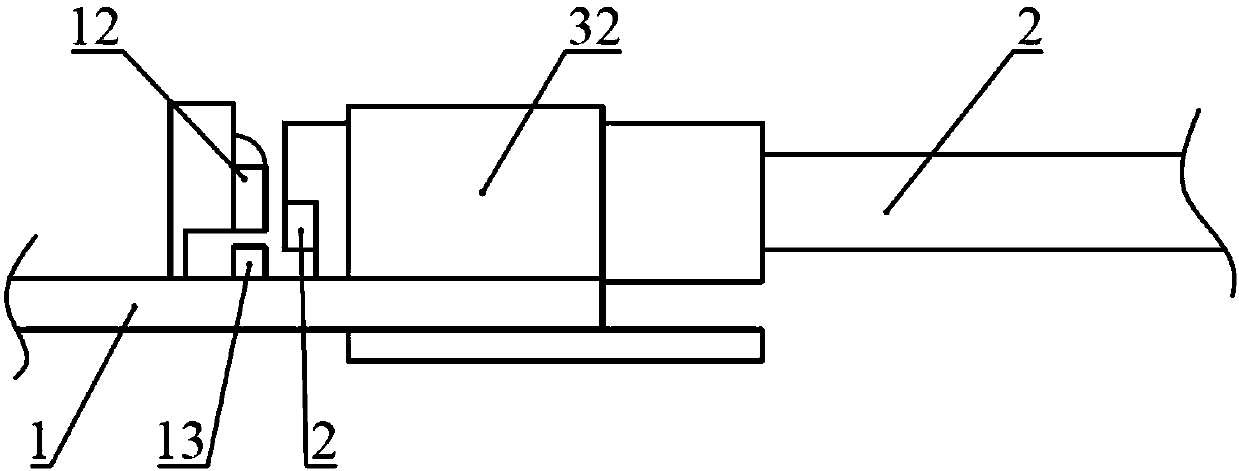
[0043] Such as figure 1 and figure 2 As shown, the display device in this embodiment also includes an optical fiber structure, the front end of the optical fiber structure is exposed to the display device, the front end of the optical fiber structure is opposite to the signal receiver 12 on the main board PCB1, and the front end of the optical fiber structure is used to receive remote control signals. The remote control signal is transmitted along the optical fiber structure, and transmitted to the signal receiver 12 by the end of the optical fiber structure, and the main board PCB1 controls the display devi...

Embodiment 2

[0065] This embodiment provides a display device whose structure is substantially the same as that of the display device in Embodiment 1. The difference from Embodiment 1 is that no front mirror 6 is provided in this embodiment, which can simplify the structure of the display device , to further reduce costs.

[0066] Specifically, as Figure 15 and Figure 16 As shown, the front end fixing sleeve 31 is fixed on the front end of the optical fiber 2 , and the front end fixing sleeve 31 protrudes from the bottom of the display device and is clipped and fixed with the face shell 5 . The remote control signal is transmitted to the signal receiver 12 on the main board PCB1 through the front end fixed sleeve 31, and realizes the remote control display device; Made of a transparent material, the light transmitted by the optical fiber 2 is transmitted from the front-end fixing sleeve 31 to realize the realistic lighting effect of the display device.

[0067] Of course, the end of t...


PUM


Abstract

The invention discloses a display device which includes a mainboard PCB, a signal receiver and a fiber structure. The signal receiver is disposed on the mainboard PCB for receiving a remote-control signal. The fiber structure is intended for transmitting the remote-control signal. A rear end of the fiber structure is connected to the mainboard PCB and is disposed opposite to the signal receiver. Afront end of the fiber structure protrudes from the display device. The display device transmits the remote-control signal through a fiber structure, one end of the fiber structure protrudes so as toreceive the remote-control signal, and the remote-control signal is transmitted to the signal receiver through the fiber structure. Since light can be in total reflection transmission through fibers,the fiber structure can be bent in the display device without influencing light transmission, and fibers have small sizes and can insert to the gaps between modules inside the display device and a housing, the signal receiver can be disposed on the mainboard PCB instead of the bottom part of the display device, or there is a need for independently disposing a PCB. Therefore, the display device can lower cost, and is conducive to the reduction of the width of a lower frame of the display device.

Description

technical field [0001] The present invention relates to the technical field of display devices, in particular to a display device that is beneficial to reducing the width of a lower frame. Background technique [0002] A display device, such as a television, is a device that outputs image or tactile information. At present, remote control technology is generally used to operate the display device. The display device is generally equipped with a remote control and a signal receiver installed inside the TV. The signal receiver is generally located at the bottom of the front of the display device. The user transmits control commands to the signal receiver through the remote control , so as to operate; in order to facilitate the user to judge whether the display device is turned on or whether there is a fault, there is also an indicator light at the bottom of the front of the display device. [0003] In the existing display device, the signal receiver and the indicator light ar...

Claims


Application Information

Patent Timeline
Patent Type & Authority Applications(China)
IPC IPC(8): H04B10/40G08C23/06
CPCG08C23/06H04B10/40
Inventor 胡灵超陈伟雄徐千正
Owner SHENZHEN SKYWORTH RGB ELECTRONICS CO LTD
Why Eureka
Try Eureka