Ligator and ligation nail for surgery

A ligation device and a technique for surgery, applied in the directions of surgery, anatomical instruments, medical science, etc., can solve the problem of low reliability of elastic snare ligation, and achieve the effects of avoiding continuous bleeding, ensuring reliability, and simple operation of instruments

Active Publication Date: 2018-02-13
SUZHOU BEINUO MEDICAL EQUIP
View PDF8 Cites 1 Cited by
  • Summary
  • Abstract
  • Description
  • Claims
  • Application Information

AI Technical Summary

Problems solved by technology

[0003] The invention provides a surgical ligature and a ligature nail, which solves the problem of low reliability of the elastic ring ligation in the treatment of hemorrhoids by the rubber ring ligation

Method used


Image

  • Ligator and ligation nail for surgery
  • Ligator and ligation nail for surgery
  • Ligator and ligation nail for surgery

Examples


Embodiment 1

[0041] Embodiment 1: A kind of surgical ligator and ligature nail

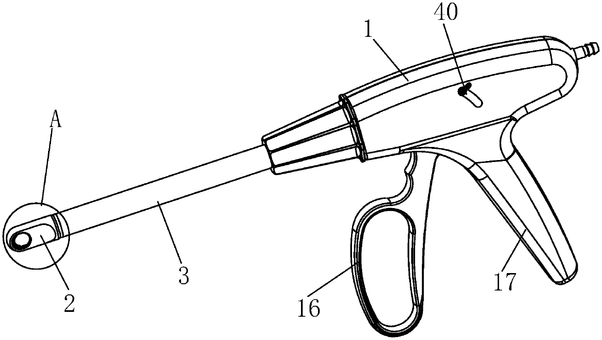
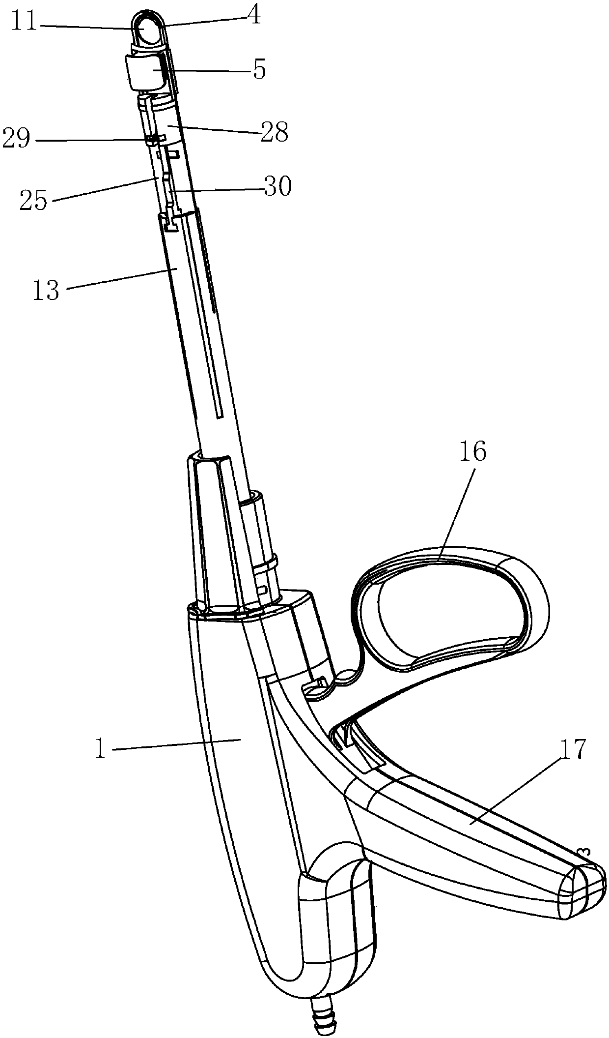
[0042] See attached Figure 1~10 and attached Figure 13~16 As shown, the surgical ligator can automatically cut after tissue ligation, and the surgical ligator includes a housing 1, a hood 2, an outer tube 3, an abutting seat 4, a nail bin 5, a nail pusher 6, a cutting Blade 25, blade spring 26, limit block 27, block support seat 28, block spring 29, driving lever 30 and driving device;

[0043] Define one end of the surgical ligator close to the operator (usually referring to the patient who needs to perform surgery) as the front end of the surgical ligator, and the other end of the surgical ligator close to the operator (usually referring to the surgeon) As the rear end of the surgical ligator, the rear end of the outer tube 3 is positioned and connected to the front end of the housing 1, that is, the outer tube 3 is positioned relative to the front end of the housing 1 in its axial direction, and the out...

Embodiment 2

[0059] Embodiment 2: a kind of surgical ligation device

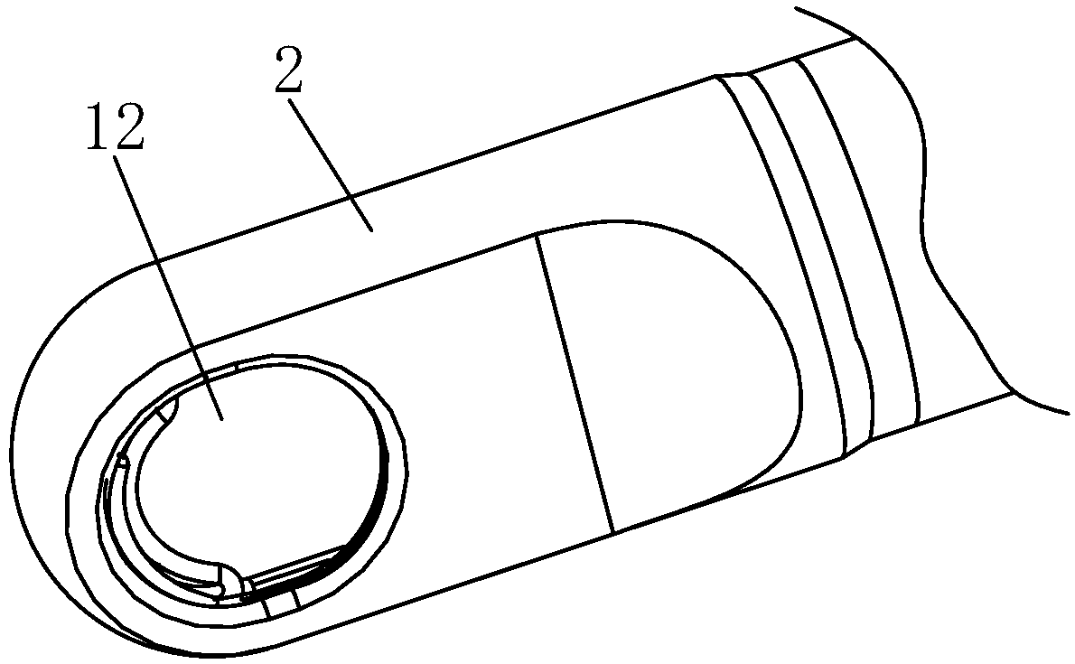
[0060] See attached Figure 11 , 12 , The difference between embodiment 2 and embodiment 1 lies in the opening structure on the nail anvil and the head cover, and the other structures of embodiment 2 are the same as embodiment 1. The plate body of the nail anvil 4 in embodiment 2 is provided with a first operating port 11 for accommodating the affected tissue adjacent to the spiral groove 9, and a first notch 19 is provided on one end surface of the plate body of the nail anchor 4 close to the spiral groove. The first notch 19 is connected with the first operating port 11; the first operating port 11 and the first notch 19 corresponding to the nail seat 4 on the side of the head cover 2 are respectively provided with a second operating port 12 and a second operating port. Two notches 20 , the second operating port 12 and the second notch 20 pass through. This structure can be used in two ways of negative pressure suc...


PUM


Abstract

Disclosed is a ligator for a surgery. The ligator is characterized by comprising a case, a hood, an outer pipe, a pin base, a pin chamber, a pin sheet and a drive device. The rear end of the outer pipe is located at the front end of the case. The hood is fixed to the front end of the outer pipe. The pin base and the pin chamber are arranged in the hood. The pin sheet is arranged in the outer pipe.The drive device is arranged in the case and can drive the pin sheet to move back and forth in the axial direction of the outer pipe. A first pin guide groove and a second pin guide groove are formedin the two sides in the width direction of a board body of the pin base. An arc section of the first pin guide groove and an arc section of the second pin guide groove are arranged on the board bodyof the pin base in the thickness direction in parallel to form a spiral groove for ligation nail forming. The front end of the pin sheet is slidably connected with the pin base. The pin chamber abutsagainst a pin placing opening. A first operation opening for accommodating tissues is formed in the pin base. A second operation opening is formed in the side of the hood. According to the ligator andthe ligation nail for the surgery, the ligation reliability of haemorrhoids and other tubular tissues is high, and continuous ligation can be carried out for multiple times.

Description

technical field [0001] The present invention relates to the field of medical devices, in particular to a surgical ligature and a ligating pin, which are used in clinical ligation of internal hemorrhoids and some small blood vessels and tubular tissues (such as the cystic duct). Background technique [0002] The more common methods of surgical treatment of hemorrhoids include hemorrhoidectomy, external stripping and internal incision, stapler hemorrhoidal circumcision and staple (PPH operation), frozen hemorrhoid therapy, rubber band ligation of hemorrhoid therapy, etc. Clinically, the treatment method for internal hemorrhoids usually adopts hemorrhoid ligation therapy with rubber rings. This method is suitable for smaller hemorrhoids. A special latex ring is placed on the root of the hemorrhoids. The whole process of ligation treatment is automated, time-saving, labor-saving, practical, simple and fast, and can effectively control the two major symptoms of hemorrhoids, namel...

Claims


Application Information

Patent Timeline
Patent Type & Authority Applications(China)
IPC IPC(8): A61B17/12A61B17/3209
CPCA61B17/12009A61B17/3209A61B2017/00398
Inventor 刘雯雯金梦
Owner SUZHOU BEINUO MEDICAL EQUIP
Why Eureka
Try Eureka