Insect trap

Pending Publication Date: 2019-05-09
SEOUL VIOSYS CO LTD
View PDF3 Cites 9 Cited by
  • Summary
  • Abstract
  • Description
  • Claims
  • Application Information

AI Technical Summary

Benefits of technology

[0010]Insect traps constructed according to exemplary embodiments of the invention are eco-friend

Problems solved by technology

In addition to damaging crops and livestock, insect pests can also affect humans by transmitting pathogens, such as malaria, dengue fever, and Japanese encephalitis.
However, chemical control has a problem of secondary pollution, and biological control or environmental control has a problem of high cost and much time and effort.
In addition, physical control using an insect trap or the like has problems, such as complicated device configuration, causing deterioration in user friendliness, and increased risk from using a high-voltage device.
However, such typical UV lamps may have high power consumption and heat generation, short lifespan, and environmental pollution due to toxic gases used in the lamps.
Howeve

Method used


Image

  • Insect trap
  • Insect trap
  • Insect trap

Examples


Example

[0235]Experimental Example 1—Control Over Angle of Vertical Section of the Air Collection Unit with Respect to the Ground.

[0236]In order to measure the frequency of escape of mosquitoes captured in the insect collection unit from the insect trap through the air collection unit outlet, depending on the angle of the vertical section of the air collection unit with respect to the ground, an experiment was conducted as follows:

[0237]More specifically, air collection units having an angle of 80°, 70°, 45°, and 30° with respect to the ground in vertical section were fabricated, and an air collection unit outlet of the air collection units had a substantially circular shape and a diameter of 50 mm, such that mosquitoes could easily escape therethrough. Then, an insect trap including the air collection unit was fabricated.

[0238]20 mosquitoes were put into an insect collection unit of the insect trap, followed by powering off the insect trap, and then the insect trap was allowed to stand for...

Example

[0240]Experimental Example 2—Control Over Vertical Length of Air Collection Unit Outlet

[0241]In order to measure the frequency of escape of mosquitoes captured in the insect collection unit from the insect trap through the air collection unit outlet, depending on the vertical length of the air corrector outlet, an experiment was conducted as follows:

[0242]More specifically, air collection units were fabricated, and an air collection unit outlet of the air collection units had a substantially circular shape and a diameter of 50 mm, such that mosquitoes could easily escape therethrough, and had a vertical length of 0 mm, 2 mm, 5 mm, or 10 mm. Then, an insect trap including the air collection unit was fabricated.

[0243]20 mosquitoes were put into an insect collection unit of the insect trap, followed by powering off the insect trap, and then the insect trap was allowed to stand for 15 hours, followed by measuring the number of mosquitoes escaping from the insect trap.

TABLE 2Number ofNum...

Example

[0245]Experimental Example 3—Control Over Shape of Air Collection Unit Rib

[0246]In order to measure the frequency of escape of mosquitoes captured in the insect collection unit from the insect trap through the air collection unit outlet, depending on the shape of the air corrector rib, an experiment was conducted as follows:

[0247]More specifically, an air collection unit including an air collection unit rib having one rod-shaped portion with a predetermined length and width (a rectangular air collection unit rib) and an air collection unit including an air collection unit rib having two rod-shaped portions each with a predetermined length and width and partially overlapping each other in the width direction (a step-shaped air collection unit rib) were fabricated. Then, an insect trap according to the present invention including each of the air collection units was fabricated.

[0248]20 mosquitoes were put into an insect collection unit of the insect trap, followed by powering off the ...


PUM


Abstract

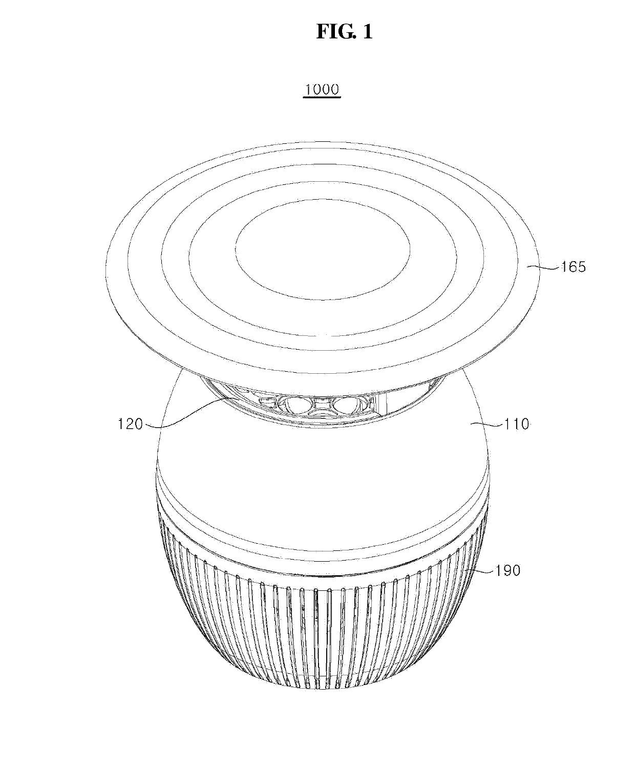
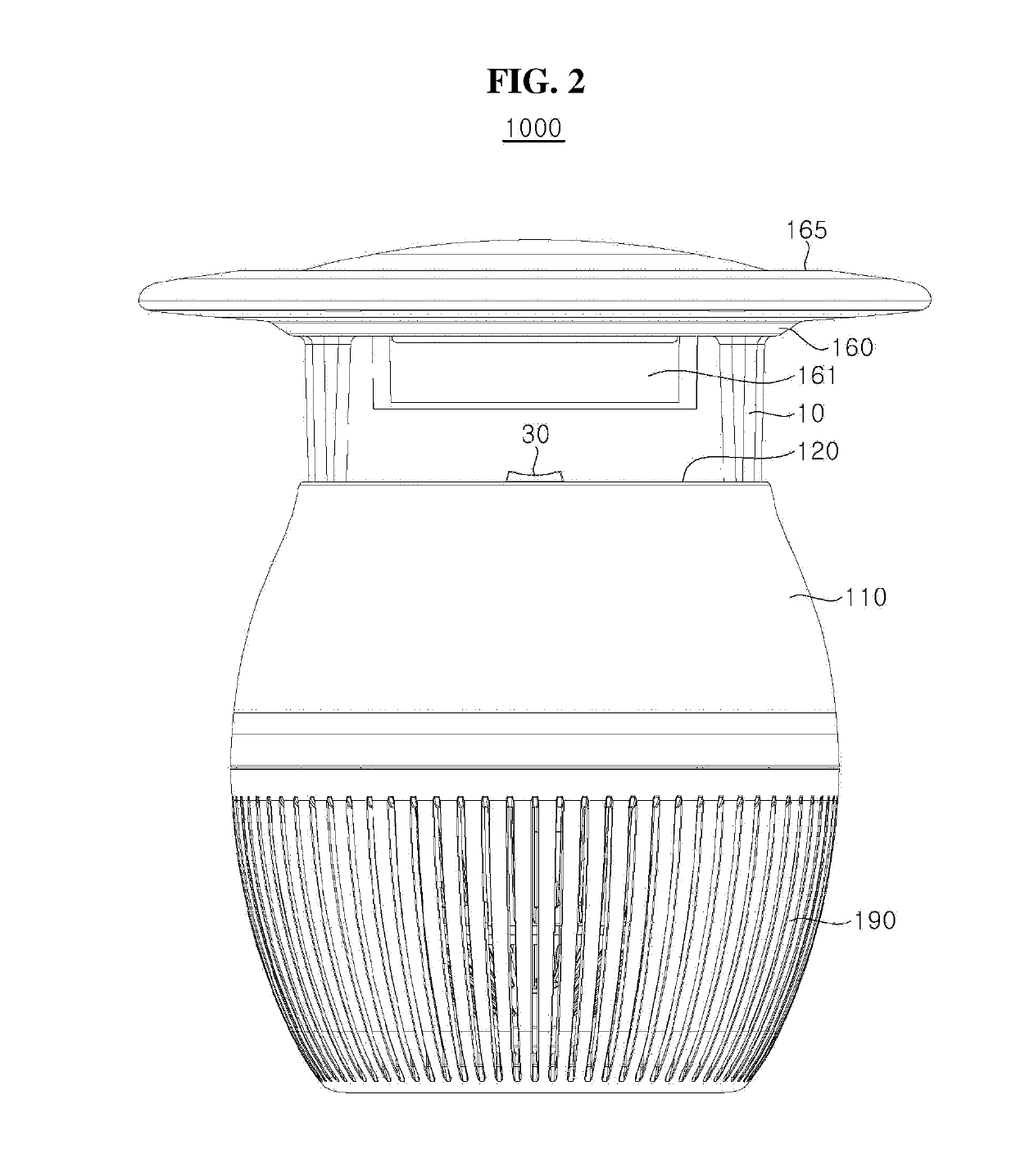
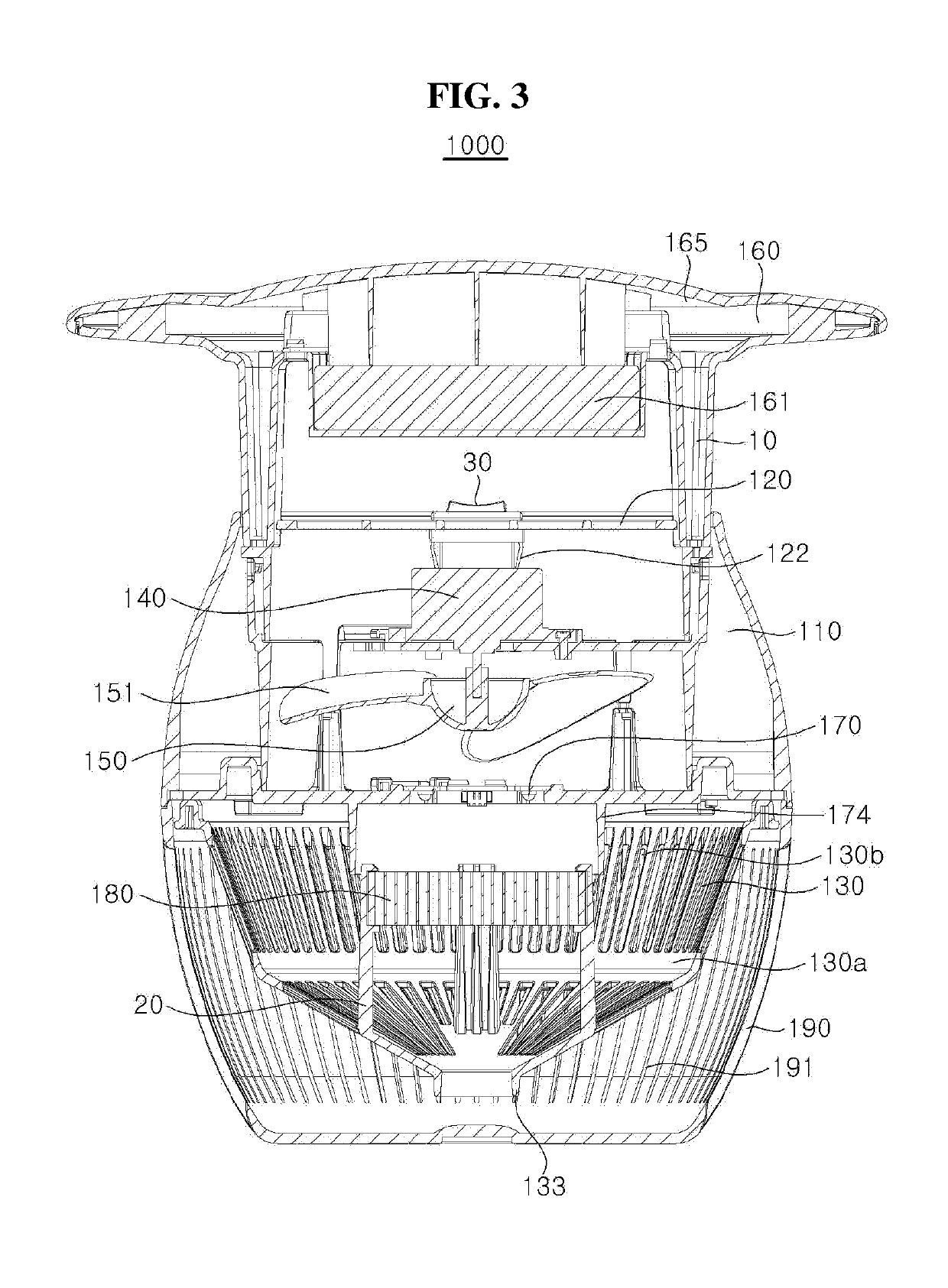
An insect trap including a main body having a suction fan, a first light emitting module mount disposed above the main body, a first light emitting module disposed on the first light emitting module mount, a roof disposed on the first light emitting module mount, an insect collection unit disposed under the main body, and an air collection unit disposed in the insect collection unit, the air collection unit having a substantially tapered shape to have a gradually decreasing diameter with an increasing distance from the suction fan, in which the first light emitting module mount includes a first light emitting module cover facing at least a portion of the first light emitting module, and the roof includes a pressing portion protruding from the roof and contacting at least one of the first light emitting module and the first light emitting module cover.

Description

CROSS REFERENCE TO RELATED APPLICATIONS[0001]This application is a Bypass Continuation of International Patent Application No. PCT / KR2017 / 007037, filed on Jul. 3, 2017, and claims priority from and the benefit of Korean Patent Application No. 10-2016-0084446, filed on Jul. 4, 2016, Korean Patent Application No. 10-2017-0040640, filed on Mar. 30, 2017, Korean Patent Application No. 10-2017-0051792, filed on Apr. 21, 2017, and Korean Patent Application No. 10-2017-0079858, filed on Jun. 23, 2017, all of which are hereby incorporated by reference for all purposes as if fully set forth herein.BACKGROUNDField[0002]Exemplary embodiments of the invention relate generally to an insect trap, and more specifically, to an insect trap including a light source and a suction fan.Discussion of the Background[0003]Recently, the population of insect pests has been increasing due to climatic and social influences, such as global warming and eco-friendly policies. In addition to damaging crops and liv...

Claims


Application Information

Patent Timeline
IPC IPC(8): A01M1/08A01M1/10A01M1/04A01M1/06
CPCA01M1/08A01M1/10A01M1/04A01M1/06A01M2200/012Y02A50/30A61L2/088
Inventor EOM, HOON SIKJO, HYUN SEUNGJU, BYEONG CHEOLCHANG, SANG HYUNKOH, MI SOCHOI, EUN MI
Owner SEOUL VIOSYS CO LTD
Why Eureka
Try Eureka