
CNC big stick machining combination clamp and clamping method

A technology of combining fixtures and fixtures, applied in the direction of manufacturing tools, metal processing equipment, metal processing machinery parts, etc., can solve problems such as defective parts, poor hole positions, and difficult positioning.

Pending Publication Date: 2018-02-13
强龙科技(苏州)有限公司
View PDF0 Cites 3 Cited by
  • Summary
  • Abstract
  • Description
  • Claims
  • Application Information

AI Technical Summary

Problems solved by technology

The defects of this type are: it is easy to cause the deformation of the workpiece hole during processing, it is not easy to locate, which affects the processing accuracy, and the shape positioning is easy to cause poor hole position and processing error of the hole position. Time is also easy to cause defective parts

Method used


Image

  • CNC big stick machining combination clamp and clamping method
  • CNC big stick machining combination clamp and clamping method

Examples


Embodiment Construction

[0017] Embodiments of the present invention are described in detail below, examples of which are shown in the drawings, wherein the same or similar reference numerals designate the same or similar elements or elements having the same or similar functions throughout. The embodiments described below by referring to the figures are exemplary only for explaining the present invention and should not be construed as limiting the present invention.

[0018] In the description of the present invention, unless otherwise specified and limited, it should be noted that the terms "installation", "connection" and "connection" should be understood in a broad sense, for example, it can be mechanical connection or electrical connection, or two The internal communication of a component can be directly connected or indirectly connected through an intermediary. Those of ordinary skill in the art can understand the specific meanings of the above terms according to specific situations.

[0019] Re...


PUM


Abstract

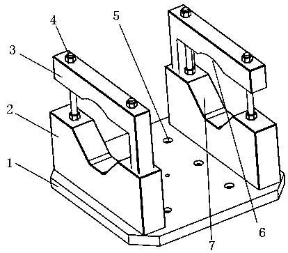
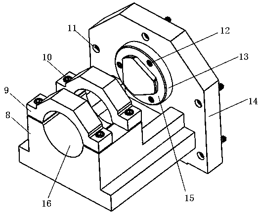
A CNC big stick machining combination clamp comprises a clamp A, a clamp B and a clamp C. The clamp B is a three-jaw chuck. Clamp mainboards are arranged above a clamp base plate of the clamp A. The left and right parts of the clamp base plate are each provided with one clamp mainboard. A fixing unit is arranged above the clamp mainboards. The fixing unit is specifically composed of pressing blocks and M16 fixing screws above the clamp mainboards; the clamp C is provided with a clamp base plate, the clamp base plate and clamp mainboards are connected to form an included angle of 90 degrees, two fixing units are arranged on the clamp mainboards, and each fixing unit specifically comprises a pressing block and M16 fixing screws. The three clamps are adopted to form the combination clamp, themachining process is divided into multiple sections, the progressive machining precision method is adopted, margin is reserved for machining, deformability of a workpiece is controlled, and the poorhole site size of a part and hole position machining errors caused by the clamping mode are avoided.

Description

technical field [0001] The invention relates to the field of mechanical manufacturing, in particular to a combined fixture and a clamping method for machining large bars by CNC. Background technique [0002] The earlier fixture type is mainly composed of two movable jaws and fixed jaws, and the type is relatively simple. The defects of this type are: it is easy to cause the deformation of the workpiece hole during processing, it is not easy to locate, which affects the processing accuracy, and the shape positioning is easy to cause poor hole position and processing error of the hole position. Time is also easy to cause defective parts. Contents of the invention [0003] The invention aims to provide a combined fixture and a clamping method for CNC machining large bar materials that ensure the verticality, coaxiality and cylindricity of products. [0004] In order to achieve the above-mentioned technical purpose, the present invention adopts the following technical soluti...

Claims


Application Information

Patent Timeline
Patent Type & Authority Applications(China)
IPC IPC(8): B23Q3/06
CPCB23Q3/06
Inventor 陈锐杰
Owner 强龙科技(苏州)有限公司
Learn More