
Pneumatic tire

A technology for pneumatic tires and tires, which is applied to tire parts, tire treads/tread patterns, transportation and packaging, etc. It can solve the problems of not being able to fully improve drainage performance, improve wet road performance, and suppress wear resistance performance and partial wear resistance, and the effect of improving drainage performance

Inactive Publication Date: 2018-02-13
SUMITOMO RUBBER IND LTD
View PDF2 Cites 3 Cited by
  • Summary
  • Abstract
  • Description
  • Claims
  • Application Information

AI Technical Summary

Problems solved by technology

[0006] However, in the pneumatic tire disclosed in the above-mentioned Patent Document 2, the water drainage performance may not be sufficiently improved especially on a wet road surface with a deep water depth, and further improvement is desired.

Method used


Image

  • Pneumatic tire
  • Pneumatic tire
  • Pneumatic tire

Examples


Embodiment Construction

[0030] Hereinafter, one embodiment of the first invention of the present invention will be described with reference to the drawings.

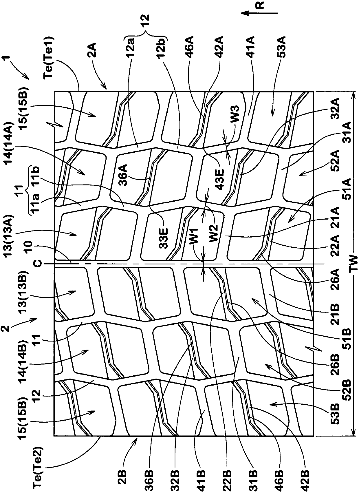
[0031] figure 1 It is a development view of the tread part 2 of the pneumatic tire 1 of this embodiment. The pneumatic tire 1 of the present embodiment is particularly preferably for heavy loads, and has a directional pattern specifying the rotational direction R of the tire on the tread portion 2 . The rotational direction R is indicated by letters, arrows, and the like, for example, on the sidewall portion.

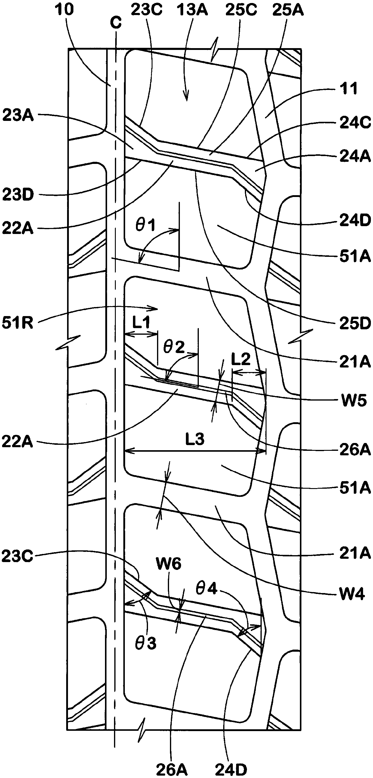
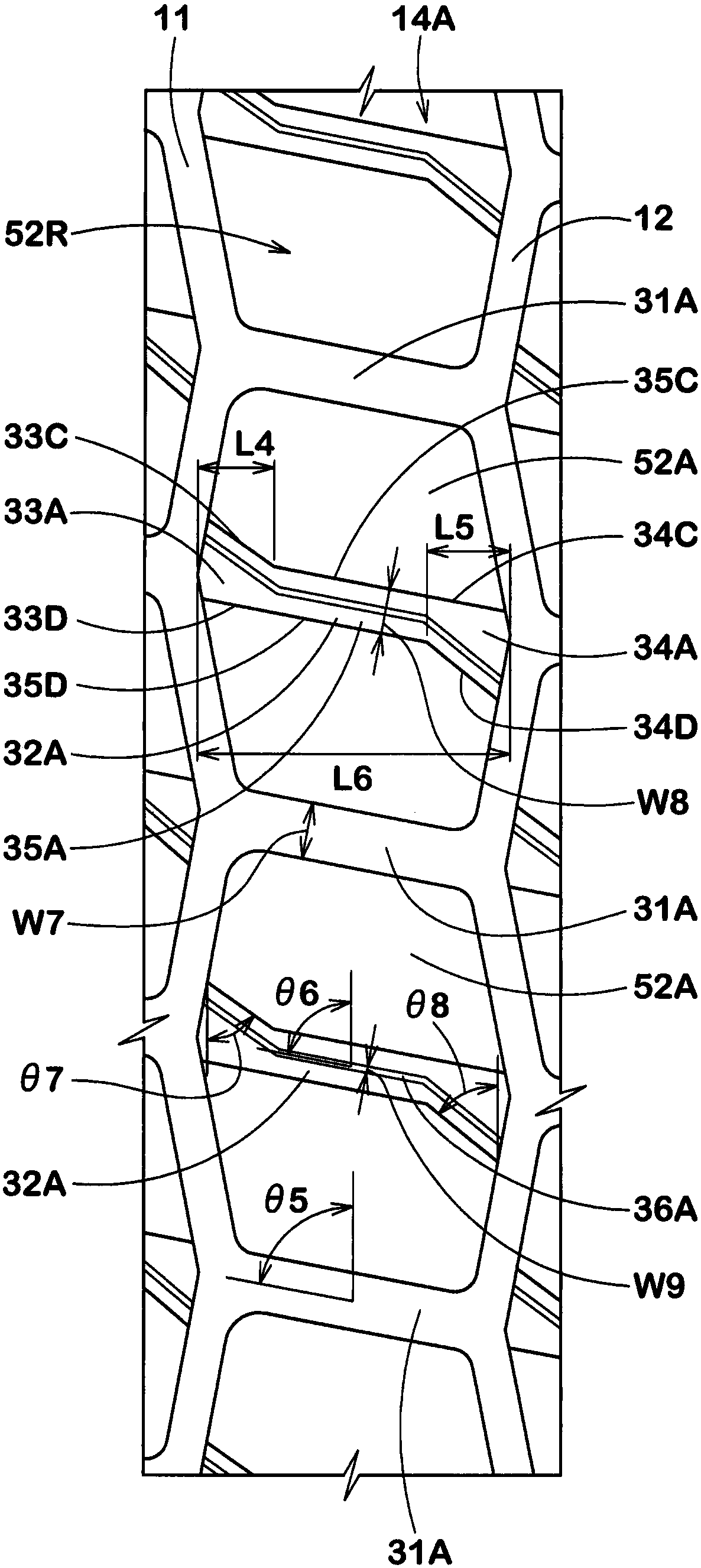
[0032] Formed on the tread portion 2 are: crown main grooves 10 continuously extending in the tire circumferential direction on the tire equator C; a pair of middle main grooves 11 continuously extending in the tire circumferential direction on both sides of the tire equator C; A pair of shoulder main grooves 12 extend continuously along the tire circumferential direction on both sides of the tire equator C. The shoulder main groove 1...


PUM


Abstract

According to the pneumatic tire provided by the invention, the wear resistance, the wear resistance and the wet path performance of the pneumatic tire can be considered in multiple directions. a tread half portion is formed between a tire equator (c) and a first tread ground terminal (TE1). a plurality of first blocks (51a) divided by a plurality of first transverse grooves (21a) are arranged onthe tire in the circumferential direction of the tire (2A) and each of the first transverse grooves (221a) faces the ground end of the first tread from the tire equator (c) side. The side is inclinedto a side opposite to the rotation direction (r) (Te1) a first shallow groove is formed in at least one of the first block and the second block. The first shallow groove is opposite to the first transverse groove (22A) is inclined in the same direction and has a ratio larger than that of the first transverse groove (21A) is small in depth (21A) in the first shallow groove. The inner end of the tire axial direction of the tire is provided with an inner expanding portion whose groove width becomes larger toward the inner side of the tire axial direction (22A) is arranged in the first shallow groove (23A), and the outer end of the tire axial direction of the tire is provided with a groove width facing the tire (22A) a shaft and an outer expanding part (24a).

Description

technical field [0001] The present invention relates to pneumatic tires. Background technique [0002] Conventionally, a pneumatic tire has been proposed in which a plurality of blocks divided by a plurality of lateral grooves are arranged in a tire circumferential direction on a tread portion for which a rotation direction is specified (for example, refer to Patent Document 1). [0003] Each of the lateral grooves is inclined toward the side opposite to the rotation direction from the tire equator side toward the tread edge side. Therefore, on a wet road surface, the water in the tread portion in the vicinity of the tire equator is discharged toward the tread contact end side through the respective lateral grooves. [0004] In the pneumatic tire disclosed in Patent Document 1, a block having a large tread portion area is used in consideration of wear resistance performance and partial wear resistance performance. However, in such blocks, the water in the tread portion of ...

Claims


Application Information

Patent Timeline
Patent Type & Authority Applications(China)
IPC IPC(8): B60C11/11
CPCB60C11/11
Inventor 井藤佳惠
Owner SUMITOMO RUBBER IND LTD
Learn More