
Hydraulic operation mechanism

A technology of hydraulic operation and hydraulic cylinder, which is applied to the power device inside the switch, etc., can solve the problems of large motor loss, affecting the normal energy consumption of the motor, and increasing the minimum power.

Inactive Publication Date: 2018-02-13
HENAN MECHANICAL & ELECTRICAL VOCATIONAL COLLEGE
View PDF5 Cites 3 Cited by
  • Summary
  • Abstract
  • Description
  • Claims
  • Application Information

AI Technical Summary

Problems solved by technology

The existing problem of this kind of pump is: the rotor is driven by the motor to rotate, corresponding to the motor, the start-up load is large, not only the power consumption but also the loss of the motor is large, and in the prior art, when the motor is started, the low pressure cavity The motor is already filled with hydraulic oil, and the start of the motor can only be completed by working on the hydraulic oil, which increases the starting load of the motor, which not only leads to an increase in the minimum power when the motor is selected, but also affects the normal energy consumption of the motor

Method used


Image

  • Hydraulic operation mechanism
  • Hydraulic operation mechanism
  • Hydraulic operation mechanism

Examples


Embodiment Construction

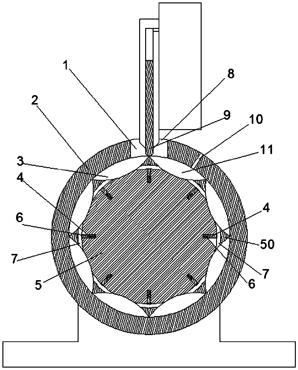
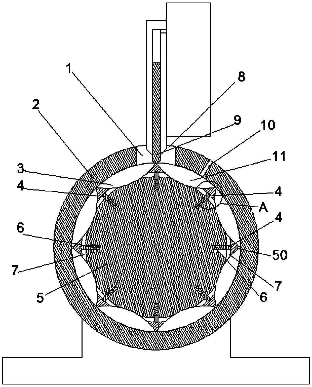
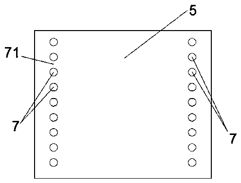
[0020] Examples of hydraulic actuators are Figure 1~9 As shown: the hydraulic operating mechanism includes a power part and an execution part. The power part includes a motor 37 and a pump 36. The execution part includes a hydraulic cylinder and an energy storage spring. The basic working principle is that the power part can pump oil into the hydraulic cylinder. The hydraulic cylinder compresses the energy storage spring to store energy. When closing is required, the energy storage spring releases energy, and the piston rod of the hydraulic cylinder drives the moving contact to move toward the static contact to realize the closing operation. The working mechanism of the hydraulic operating mechanism belongs to the prior art and will not be described in detail here. The improvement of this invention lies in the following parts.

[0021] The pump 36 includes a pump body 2 with a cylindrical hole inner cavity. The pump body 2 is provided with a rotor 5 whose rotation axis extend...


PUM


Abstract

The invention relates to a hydraulic operation mechanism. A power part of the hydraulic operation mechanism comprises a pump, wherein the pump comprises a rotor; the rotating axial line of the rotor extends in the front and back direction; the cross section of the rotor is of a polygonal structure; convex edges tangential with a cylindrical hole are formed between the two adjacent edges; a liquidinlet hole and a liquid outlet hole which are separated by a separation plate are formed in the pump body; one end of the separation plate is matched with the outer peripheral surface of the rotor ina slide jacking and pushing manner. The hydraulic operation mechanism is characterized in that an oil guide passage communicating with the peripheral two sides of the convex edge is arranged in the position of each convex edge; a sealing and blocking block is assembled on the rotor in the radial direction of the rotor in a guide moving way; the sealing and blocking block has a first position for avoiding the oil guide passage in the moving stroke and a second position for sealing and blocking the oil guide passage through the outward movement under the effect of centrifugal force; a spring enabling the sealing and blocking block to be positioned in the first position through the acting force exertion on the sealing and blocking block is arranged on the rotor. The invention provides the hydraulic operation mechanism capable of reducing the motor starting load.

Description

technical field [0001] The invention relates to a hydraulic operating mechanism. Background technique [0002] As a common electrical equipment, the circuit breaker is widely used. The circuit breaker includes an arc extinguishing chamber, moving contacts and static contacts arranged in the arc extinguishing chamber. The circuit breaker also includes a transmission connection with the moving contact to drive the moving contact. The hydraulic operating mechanism that realizes the opening and closing of the moving contact and the static contact by the action of the contact. The hydraulic operating mechanism includes a power part and an execution part. The power part of the hydraulic operating mechanism includes a motor and a pump. The execution of the hydraulic operating mechanism The part includes a hydraulic cylinder and an energy storage spring. The power part can pump oil into the hydraulic cylinder. The hydraulic cylinder compresses the energy storage spring to store ener...

Claims


Application Information

Patent Timeline
Patent Type & Authority Applications(China)
IPC IPC(8): H01H3/24H01H3/26
CPCH01H3/24H01H3/26
Inventor 邢仁周徐鹏飞王天一李立申超群张卓
Owner HENAN MECHANICAL & ELECTRICAL VOCATIONAL COLLEGE
Learn More