
Fastening device used for fixing cable

A technology for fastening devices and fixing wires, which is applied in the direction of electrical components, etc., can solve the problems of low assembly efficiency, lengthened working hours, and increased manufacturing costs, and achieve the effects of saving costs, high assembly efficiency, and avoiding distortion

Pending Publication Date: 2018-02-13
CONTINENTAL AUTOMOTIVE CORP LIANYUNGANG CO LTD
View PDF4 Cites 3 Cited by
  • Summary
  • Abstract
  • Description
  • Claims
  • Application Information

AI Technical Summary

Problems solved by technology

In the existing design, the fastening device and the wire harness are tightly fixed, that is to say, the fastening device cannot be rotated after being installed on the wire harness, and it is difficult to accurately control the installation angle of the fastening device in production assembly, and The operator may also have the wrong angle when assembling
When the installation angle of the fastening device is wrong, the wire harness between two adjacent fastening devices will be twisted, and this distortion will easily lead to the breakage of the wire harness during use
[0003] In order to avoid cable or wire twisting as much as possible, it is generally necessary to design the tooling fixture according to the required angle when assembling the fastening device to control the phase of adjacent fastening devices, and usually the cables between two adjacent fastening devices Or a line of a different color is drawn on the wire. The operator needs to check this line to determine whether the cable or wire is twisted when installing the wire harness, resulting in increased manufacturing costs, longer man-hours, and low assembly efficiency.

Method used


Image

  • Fastening device used for fixing cable
  • Fastening device used for fixing cable
  • Fastening device used for fixing cable

Examples


Embodiment 1

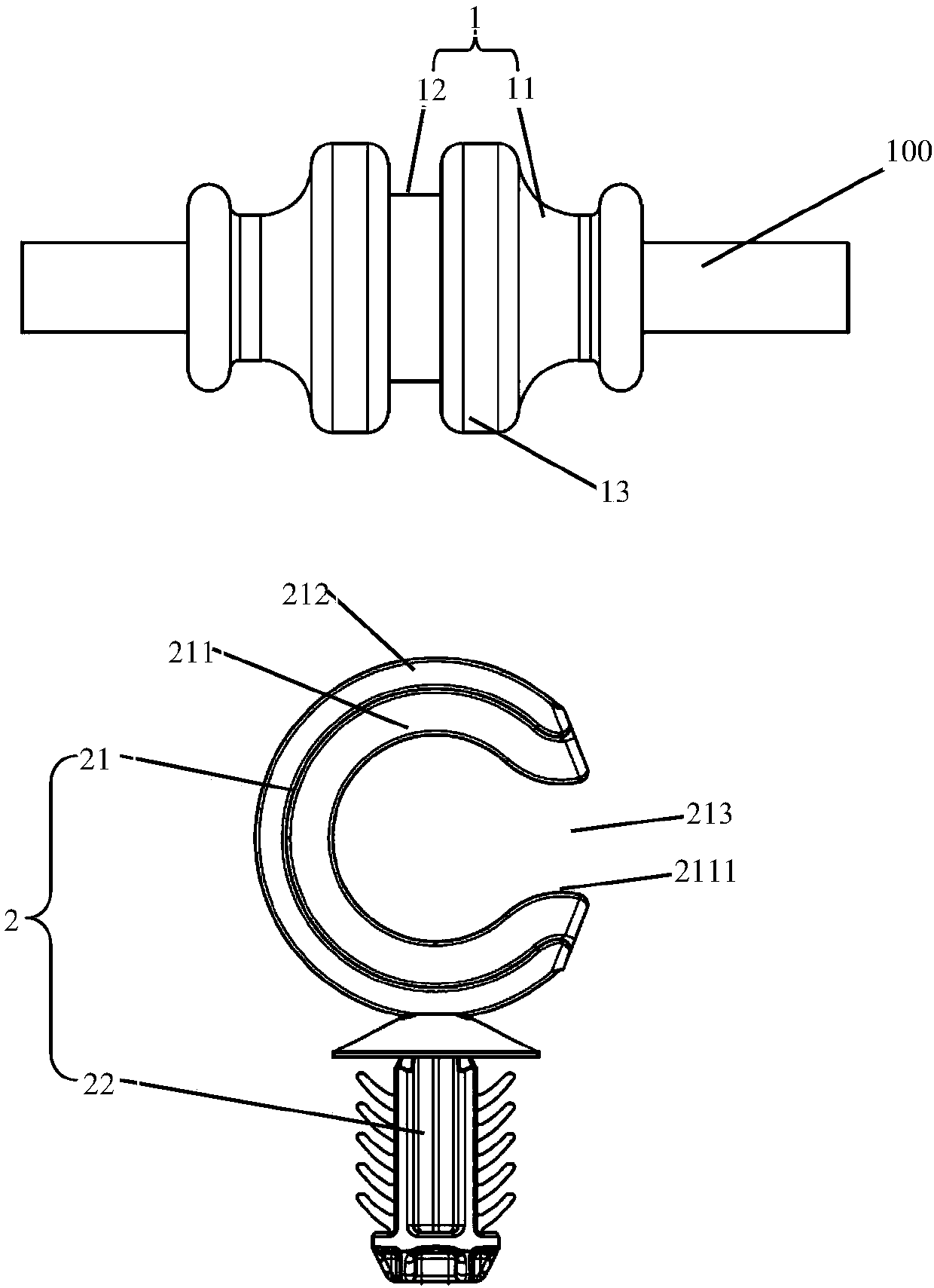
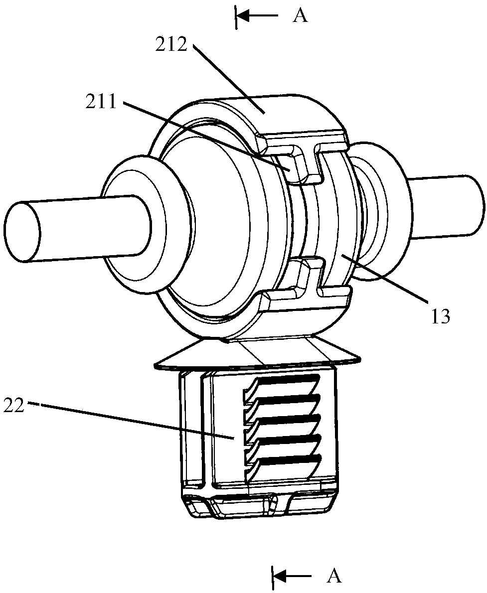
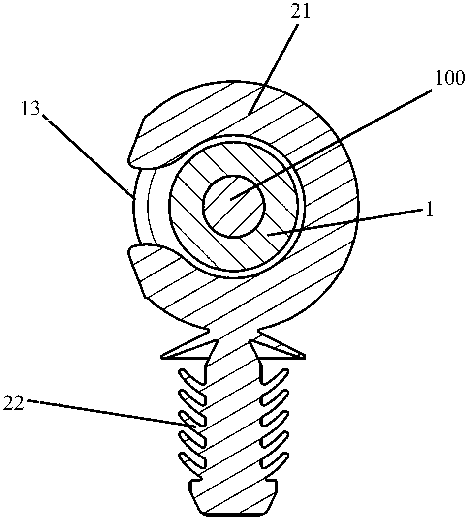
[0024] see Figure 1 to Figure 3 , the fastening device for fixing the wire harness 100 includes a locking piece 1 and a fixing piece 2 , the locking piece 1 is made of rubber, and is fixed to the wire harness 100 by injection molding. The fixing part 2 is one piece and is injection molded from nylon. The locking part 1 includes a locking part 11 and a first guiding part 12 for fixing the wire harness 100, and the fixing part 2 includes a second guiding part 21 and a holding part for connecting the fastening device to a fixed position 22 , the first guide part 12 is slidingly matched with the second guide part 21 so as to guide the fixing part 2 to rotate axially around the wire harness 100 . When assembling, rotating the fixing part 2 according to the actual situation can effectively avoid twisting of the wire harness, and the cost is low and the assembly is convenient.

[0025] The first guide part 12 is a guide groove extending circumferentially along the locking member 1...

Embodiment 2

[0028] see Figures 4 to 6 , the difference between this embodiment and Embodiment 1 is that the second guide part 21 has two sections 210, one side of the two sections 210 is connected by a hinge part 215, and the other side is connected by an open or The locking latch mechanism 216 is connected. The locking mechanism 216 includes a buckle part 217, two position-limiting parts 218 cooperating with the buckle part 217, and a buckle slot 219 for accommodating the buckle part 217. The buckle part 217 has a guide surface 2171, and two position-limiting parts The part 218 is oppositely disposed and has a guide surface 2181. The locking mechanism 216 also includes an elastic arm 214, wherein a limiting part 218 is arranged at the end of the elastic arm 214. When the elastic arm 214 is not elastically deformed, the two The spacing between each limiting portion 218 is smaller than the width of the locking portion 217 . When assembling, the fixing part 2 is sleeved on the locking pa...


PUM


Abstract

The invention relates to a fastening device used for fixing a cable. The fastening device comprises a locking component and a fixing component, the locking component comprises a locking part used forfixing wiring harness and a first guide part, the fixing component comprises a second guide part and a keeping part used for connecting the fastening device to a fixed position, and the first guide part and the second guide part are in sliding fit to guide the fixing component in rotating in the axial direction around the wiring harness. Due to the fact that the first guide part and the second guide part are in sliding fit to guide the fixing component in rotating in the axial direction around the wiring harness, during assembly, the fixing component can be rotated according to actual conditions, and torsion of the wiring harness can be effectively avoided.

Description

technical field [0001] The invention relates to a fastening device for fixing cables. Background technique [0002] When the wire harness is installed on the vehicle body or chassis through the fastening device, the direction of each fastening device is different, which requires that the fastening device be installed on the wire harness according to the angle actually required. In the existing design, the fastening device and the wire harness are tightly fixed, that is to say, the fastening device cannot be rotated after being installed on the wire harness, and it is difficult to accurately control the installation angle of the fastening device in production assembly, and The operator may also have the wrong angle when assembling. When the installation angle of the fastening device is wrong, the wire harness between two adjacent fastening devices will be twisted, and this twist will easily lead to the breakage of the wire harness during use. [0003] In order to avoid cabl...

Claims


Application Information

Patent Timeline
Patent Type & Authority Applications(China)
IPC IPC(8): H02G3/02
CPCH02G3/02
Inventor 陈志金
Owner CONTINENTAL AUTOMOTIVE CORP LIANYUNGANG CO LTD
Learn More