Lamp pole longitudinal joint welding mechanism

A welding and lamp pole technology, applied in welding equipment, arc welding equipment, manufacturing tools, etc., can solve the problems of cost, difficulty in ensuring the distance between welding wire and welding seam, difficulty in operation, etc., and achieve the effect of ensuring quality

Pending Publication Date: 2018-02-16
JIANGSU TEWEI MACHINE TOOL MFG
View PDF8 Cites 4 Cited by
  • Summary
  • Abstract
  • Description
  • Claims
  • Application Information

AI Technical Summary

Problems solved by technology

Its disadvantages are: the walking support structure of the device needs auxiliary rails to walk, so it is not only costly, but also difficult to operate, and it is difficult for the device to ensure the distance between the welding wire and the welding seam

Method used


Image

  • Lamp pole longitudinal joint welding mechanism

Examples


Embodiment Construction

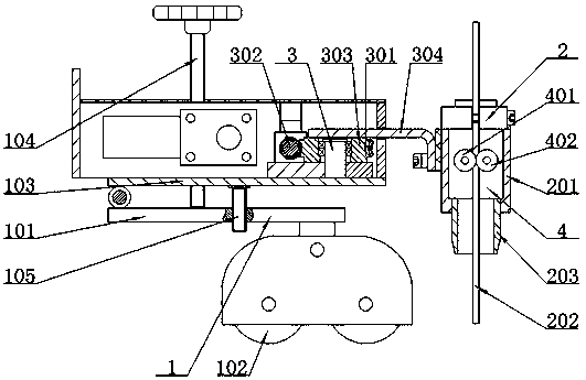
[0014] like figure 1 As mentioned above, it is a light pole longitudinal seam welding mechanism, which includes a guide mechanism 1 located in the light pole to be welded and a weld seam mechanism 2 connected to the guide mechanism 1. In order to ensure that the welding wire 202 reaches the welding seam during the welding The welding seam mechanism 2 includes a housing 201, the lower port of the housing 201 is connected with a welding tip 203 for positioning the welding wire 202, and the housing 201 is provided with a wire feeding mechanism 4, in order to ensure that the welding wire 202 reaches the welding seam during the welding process. The distance between them remains unchanged to ensure that the welding seam mechanism 2 works reliably. The wire feeding mechanism 4 includes active feeding wheels 401 and driven feeding wheels 402 that cooperate with each other. The active feeding wheels 401 are connected through the transmission of the wire feeding motor. Rolling with the ...


PUM


Abstract

The invention relates to a lamp pole longitudinal joint welding mechanism comprising a guide mechanism located in a to-be-welded lamp pole, and a welding joint mechanism connected to the guide mechanism. The guide mechanism comprises a plate. A guide wheel walking in a welding joint is connected to the bottom face of the plate. A connecting plate is hinged to the top face. A stud is in screw connection with the connecting plate. The lower end of the stud abuts against the upper surface of the plate and is used for adjusting the included angle between the plate and the connecting plate. The connecting plate is connected with the welding joint mechanism through a welding swing mechanism. Due to the fact that the guide wheel is matched with the welding joint, the effect that the welding jointmechanism conducts welding effectively along the welding joint is ensured while the guide wheel combs the welding joint. In addition, due to existing of the welding swing mechanism, the effect that awelding wire of the welding joint mechanism is welded in a zigzag shape in the welding joint is ensured, and thus the quality of the welded gap is ensured.

Description

technical field [0001] The invention relates to the technical field of light pole forming, in particular to a light pole longitudinal seam welding mechanism. Background technique [0002] The existing Chinese patent database discloses the submerged arc automatic welding machine head structure capable of welding the inner longitudinal seam of cylindrical steel parts. The date of authorization announcement is: 2012.04.25. The device includes a welding nozzle. The welding nozzle is installed at the bottom of the front-end layout plate. A probe rod with a bent front end is welded on the top, the rear end of the probe rod is used to be fixedly connected to the main body of the welding machine, and the lower part of the front end arrangement plate is provided with a walking support structure. Its shortcoming is: the walking supporting structure of this device needs auxiliary track to just can walk, therefore not only costly, and difficult to operate, and this device is difficult ...

Claims


Application Information

Patent Timeline
Patent Type & Authority Applications(China)
IPC IPC(8): B23K9/025B23K9/18B23K9/12B23K9/133
CPCB23K9/025B23K9/12B23K9/133B23K9/18
Inventor 顾平顾冬平张俊
Owner JIANGSU TEWEI MACHINE TOOL MFG
Why Eureka
Try Eureka