
Efficient movable household clothes hanger

A kind of clothes hanger, high-efficiency technology, applied in home appliances, applications, washing devices, etc., can solve the problems of poor drying effect of clothes, poor drying effect, not particularly good ventilation effect, etc.

Active Publication Date: 2018-02-16
盐城新汇村镇建设发展有限公司
View PDF8 Cites 2 Cited by
  • Summary
  • Abstract
  • Description
  • Claims
  • Application Information

AI Technical Summary

Problems solved by technology

[0002] Nowadays, people live in high-rise commercial buildings, and they set up some drying racks on the balcony to dry clothes, but the effect of drying clothes on the inside of the general balcony is not good, because it is half-open, and the time for sunlight to shine is limited, so it is often necessary to build Some movable hanging clothes hangers protruding from the outside of the balcony are fixed on the outer wall by bolts and other fixtures, and this kind of ordinary clothes hangers are usually hung on them one by one through hangers, and the clothes are usually arranged in a row. In a row, this will lead to poor drying effect of the clothes in the middle, because the clothes on the left and right sides will be blocked, and because this kind of clothes hanger is suspended on the outside of the outer wall, it cannot be made too long, and it needs to be stretched by human hands. In the long range, it is convenient for people to take it, but because it is too close to the cavity, the use space is not large, and the ventilation effect is not particularly good

Method used

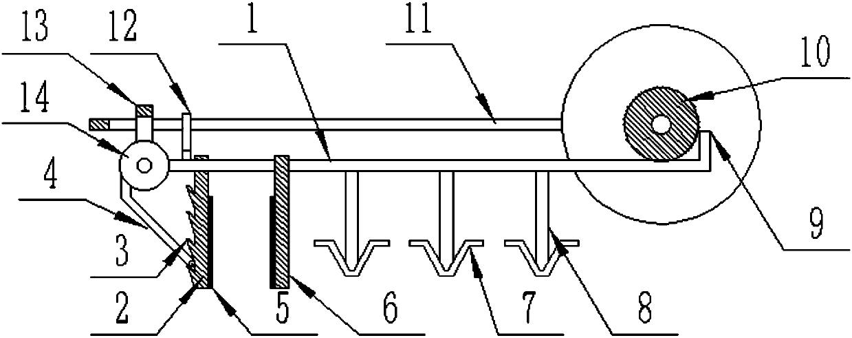
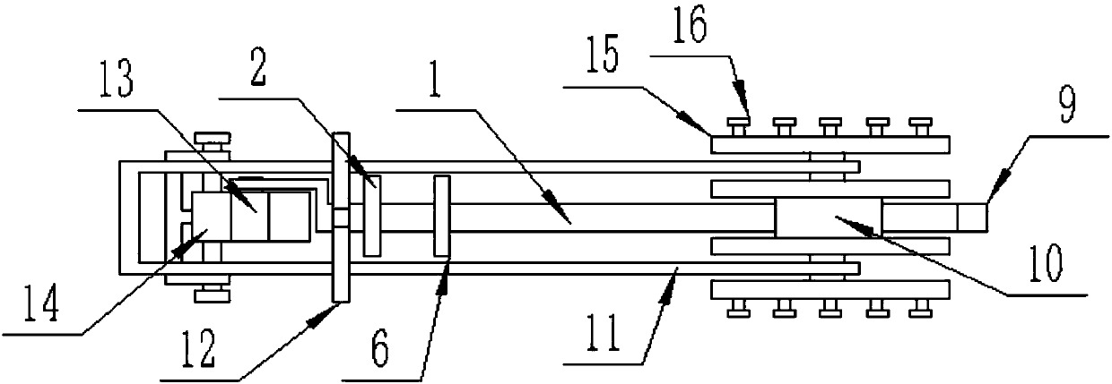
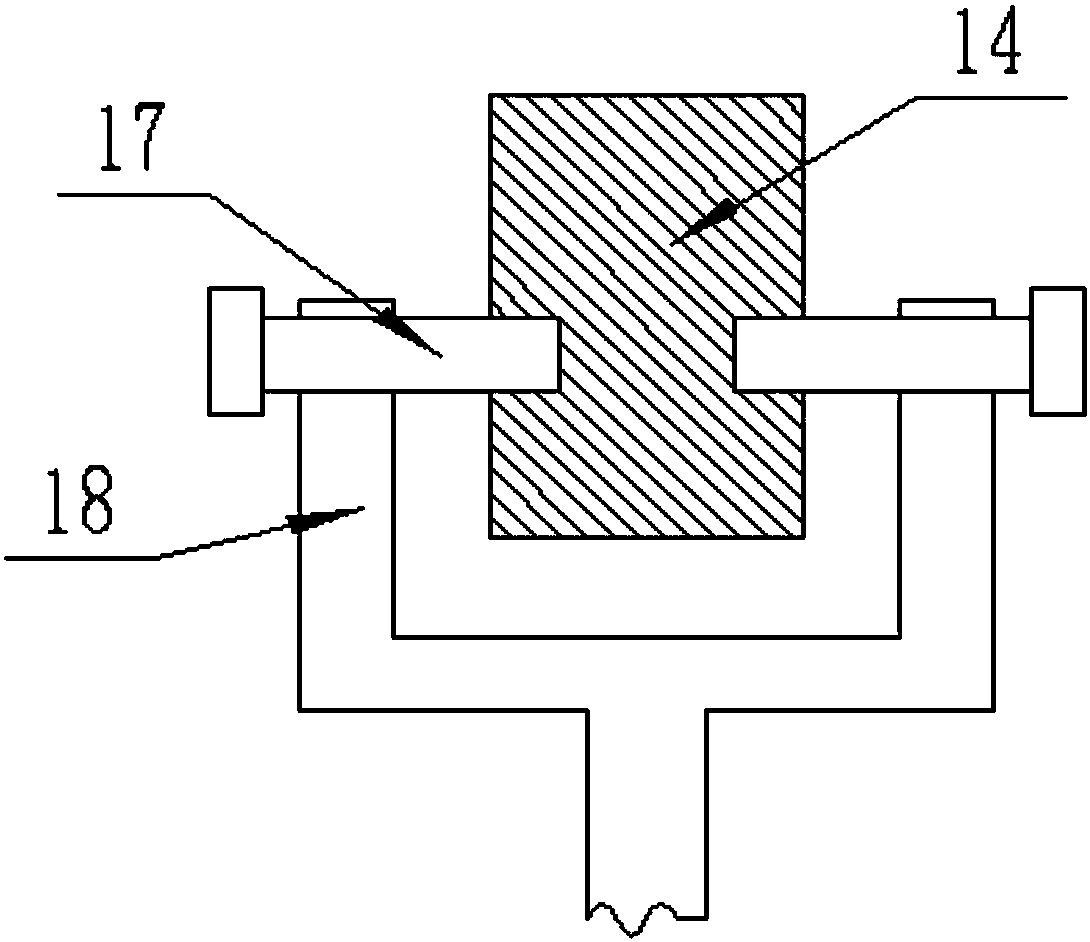

Image

  • Efficient movable household clothes hanger
  • Efficient movable household clothes hanger
  • Efficient movable household clothes hanger

Examples


Embodiment Construction

[0018] The technical solution of this patent will be further described in detail below in conjunction with specific embodiments.

[0019] Embodiments of the present patent are described in detail below, examples of which are shown in the drawings, wherein the same or similar reference numerals designate the same or similar elements or elements having the same or similar functions throughout. The embodiments described below by referring to the figures are exemplary and are only used for explaining the patent, and should not be construed as limiting the patent.

[0020] In the description of this patent, it is to be understood that the terms "center", "upper", "lower", "front", "rear", "left", "right", "vertical", "horizontal", The orientation or positional relationship indicated by "top", "bottom", "inner", "outer", etc. is based on the orientation or positional relationship shown in the drawings, and is only for the convenience of describing this patent and simplifying the des...


PUM


Abstract

The invention provides an efficient movable household clothes hanger and belongs to the field of household clothes drying. The hanger comprises a support rod, a clamping rod and a U-shaped pull rod; the support rod is horizontal, and the left end of the support rod is fixedly connected with a fixed plate; the left end of the support rod of the left side of a movable plate is connected with a turntable through a rotation shaft, and the rotation shaft of the turntable is located in the front-and-back direction; the movable plate and the fixed plate are used for jointly clamping a balcony handrail to fix the whole clothes hanger; after the movable plate and the fixed plate clamp the balcony handrail, the turntable is turned counterclockwise to make the ends of the clamping rod to support themovable plate, and therefore the movable plate firmly clamps the balcony handrail; the clamping rod slides upwards from the lower side of the left end face of the movable plate to be clamped in a corresponding inverted groove to closely support the movable plate as the turntable is turned counterclockwise. At the same time, the inverted groove prevents the clamping rod from dropping from the movable plate and fixes the movable plate. When the clothes hanger needs to be dismounted, movable bolts at the two sides of a U-shaped support are removed from the turntable, the clamping rod is taken down, and therefore the movable plate is loosened.

Description

technical field [0001] The invention relates to a household clothes drying tool, in particular to a household high-efficiency movable clothes drying rack. Background technique [0002] Nowadays, people live in high-rise commercial buildings, and they set up some drying racks on the balcony to dry clothes, but the effect of drying clothes on the inside of the general balcony is not good, because it is half-open, and the time for sunlight to shine is limited, so it is often necessary to build Some movable hanging clothes hangers protruding from the outside of the balcony are fixed on the outer wall by bolts and other fixtures, and this kind of ordinary clothes hangers are usually hung on them one by one through hangers, and the clothes are usually arranged in a row. In a row, this will lead to poor drying effect of the clothes in the middle, because the clothes on the left and right sides will be blocked, and because this kind of clothes hanger is suspended on the outside of t...

Claims


Application Information

Patent Timeline
IPC IPC(8): D06F57/12
CPCD06F57/12
Inventor 不公告发明人
Owner 盐城新汇村镇建设发展有限公司
Learn More