
Lens cone bottom inner wall with flatting effect

A lens barrel and functional technology, which is applied to the inner wall of the bottom of the lens barrel, can solve the problem that the degree of attenuation cannot meet the demand, and achieve the effects of weakening energy, increasing push-off force, and eliminating stray light

Pending Publication Date: 2018-02-16
辽宁中蓝光电科技有限公司
View PDF0 Cites 2 Cited by
  • Summary
  • Abstract
  • Description
  • Claims
  • Application Information

AI Technical Summary

Problems solved by technology

At present, the usual measure is to atomize the surface of the inner wall, but this can only reduce the stray light for some lenses, but this degree of reduction sometimes cannot meet the demand

Method used


Image

  • Lens cone bottom inner wall with flatting effect
  • Lens cone bottom inner wall with flatting effect
  • Lens cone bottom inner wall with flatting effect

Examples


Embodiment Construction

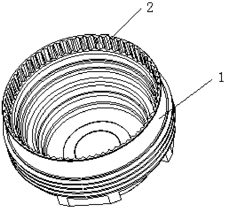
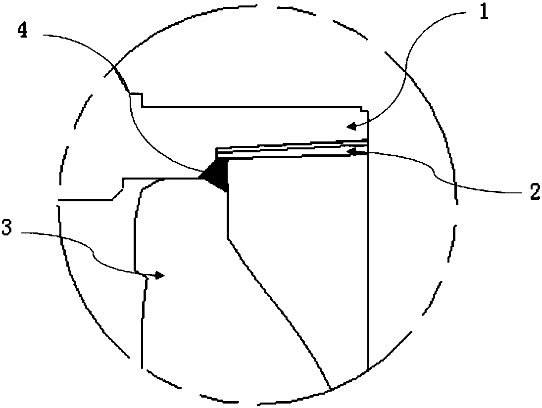
[0014] like Figure 1-Figure 2 Shown is an inner wall at the bottom of the lens barrel with a matting effect, and the inner wall at the bottom of the lens barrel 1 is provided with a pattern 2 in a wave shape;

[0015] The pattern 2 is provided with crests and troughs.

[0016] The distance between the pattern 2 and the pattern is 0.15mm-0.3mm.

[0017] The crests and troughs of the pattern 2 are provided with rounded corners of 0.05mm-0.1mm.

[0018] The depth direction of the pattern 2 is provided with a demoulding angle of 3°-5°.

[0019] Dispense glue 4 where the lens 3 is in contact with the pattern.


PUM


Abstract

The invention discloses a lens cone bottom inner wall with a flatting effect. Wavy decorative patterns are arranged on the lens cone bottom inner wall; and the decorative patterns are provided with wave crests and wave troughs. The lens cone bottom inner wall is simple to machine and low in cost, the lens cone bottom inner wall is designed to be provided with the wavy decorative patterns, the reflection direction of a light beam can be changed, the light beam is reflected in a dispersed state, and the energy of reflected light is greatly weakened, so that the purpose of eliminating stray lightis reached.

Description

technical field [0001] The invention relates to the field of mobile phone cameras, in particular to an inner wall at the bottom of a lens barrel with a light extinction effect. Background technique [0002] At present, the requirements for lens stray light in the mobile phone market are becoming more and more stringent, because there are many components that make up high-end lenses, and there are many factors that produce stray light. At present, the inner wall of the bottom of the lens barrel is usually designed in a ring shape. When incident light hits the lens barrel, the light is reflected in a single direction, and the converging strong reflected beam hits the image surface, resulting in strong stray light. In order to eliminate stray light, some measures to prevent and eliminate stray light are usually done on the surface of the inner wall of the component. At present, the usual measure is to atomize the surface of the inner wall, but this can only reduce the stray li...

Claims


Application Information

Patent Timeline
Patent Type & Authority Applications(China)
IPC IPC(8): G03B11/00G03B30/00
CPCG03B11/00
Inventor 鲁冲尹立红
Owner 辽宁中蓝光电科技有限公司
Learn More