
Display panel and display device

Active Publication Date: 2018-02-16
SHANGHAI TIANMA MICRO ELECTRONICS CO LTD
View PDF10 Cites 43 Cited by
  • Summary
  • Abstract
  • Description
  • Claims
  • Application Information

AI Technical Summary

Problems solved by technology

[0003] Embodiments of the present invention provide a display panel and a display device, which are used to solve the problem of poor brightness uniformity of micro-luminescent display panels in the prior art

Method used


Image

  • Display panel and display device
  • Display panel and display device
  • Display panel and display device

Examples


Embodiment Construction

[0028] In order to make the purpose, technical solutions and advantages of the embodiments of the present invention clearer, the technical solutions in the embodiments of the present invention will be clearly and completely described below in conjunction with the drawings in the embodiments of the present invention. Obviously, the described embodiments It is a part of embodiments of the present invention, but not all embodiments. Based on the embodiments of the present invention, all other embodiments obtained by persons of ordinary skill in the art without creative efforts fall within the protection scope of the present invention.

[0029] Terms used in the embodiments of the present invention are only for the purpose of describing specific embodiments, and are not intended to limit the present invention. As used in the embodiments of the present invention and the appended claims, the singular forms "a", "said" and "the" are also intended to include the plural forms unless th...


PUM


Abstract

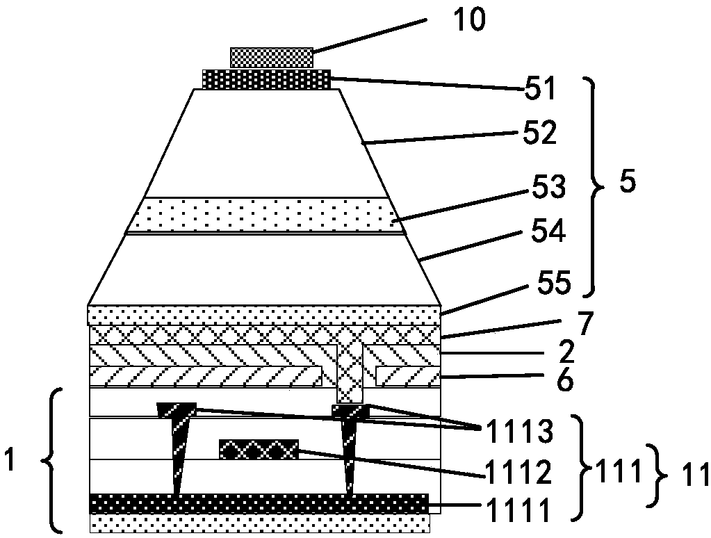
The embodiment of the invention provides a display panel and a display device. The display panel comprises a first insulating layer located on a substrate, a barricade layer located on the side, awayfrom the substrate, of the first insulating layer, a metal reflection layer, micro light emitting diodes located in separation-levee open structures respectively and a metal heat-dissipating layer connected with the metal reflection layer, wherein the barricade layer comprises the multiple separation-levee open structures, the metal reflection layer comprises multiple metal reflection structures corresponding to the separation-levee open structures in a one-to-one mode, and the micro light emitting diodes are arranged to be insulated from the metal reflection structures. According to the display panel and the display device, due to the fact that heat on the metal reflection layer can be conducted to the metal heat-dissipating layer and dissipated through the metal heat-dissipating layer, and that is to say, cooling can be conducted on the micro light emitting diodes by the metal heat-dissipating layer to reduce the temperature differences of the micro light emitting diodes in the different positions, the luminescent performance of the micro light emitting diodes in the different positions is almost the same, and then the evenness of the lightness of the display panel is improved.

Description

technical field [0001] The present invention relates to the field of display technology, in particular to a display panel and a display device. Background technique [0002] In the micro light-emitting display panel, the micro light-emitting diodes will generate heat during operation, and when the micro light-emitting display panel displays images, the brightness of the micro light-emitting diodes at different positions may be different, wherein the micro light-emitting diodes with higher brightness The more heat generated, the temperature of the micro-LEDs at different positions is different. Since the luminous performance of the micro-LEDs is greatly affected by the temperature, when the temperatures of the micro-LEDs at different positions are different, the temperature of the micro-LEDs at different positions is different. The luminous properties of the micro light emitting diodes on the micro light emitting diodes are different, which makes the brightness uniformity of ...

Claims


Application Information

Patent Timeline
Patent Type & Authority Applications(China)
IPC IPC(8): G09F9/33H05K7/20
CPCG09F9/33H05K7/20954
Inventor 楼均辉迟霄应变
Owner SHANGHAI TIANMA MICRO ELECTRONICS CO LTD
Learn More