Unpowered long-rod part storage device capable of conducting clamping automatically
A technology for storage devices and long rods, which is applied in the field of non-powered automatic clamping long rod storage devices, which can solve the problems of small cross-section and large length, and achieve the effects of large bearing capacity, convenient layout and compact structure
- Summary
- Abstract
- Description
- Claims
- Application Information
AI Technical Summary
Problems solved by technology
Method used
Image
Examples
Embodiment 1
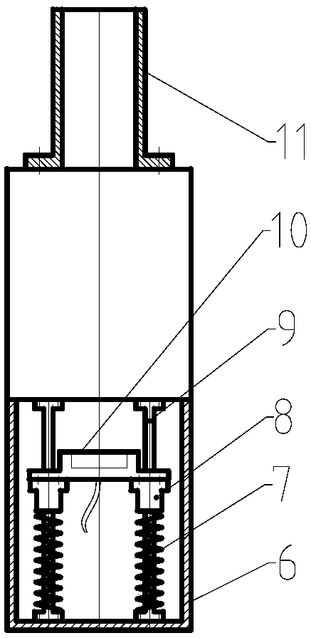
[0020] See attached figure 1 , 2 , 3, the non-powered automatic clamping long rod storage device includes a fixing mechanism 1, a connecting frame 2, a linkage cable 3, and a supporting mechanism 4, and the fixing mechanism 1 includes a mounting seat 6, a return spring I7, a guide block 8, Guide rod 9, support frame 10, protective cover 11, guide block 8 and guide rod 9 cooperate to form a moving pair, mounting seat 6 is fixed, has two sets of guiding mechanisms, the upper and lower ends of guide rod 9 are respectively fixed with mounting seat 6, The support frame 10 is connected with the guide block 8 and moves with the guide block 8. The fixing mechanism 1 has two return springs I7.
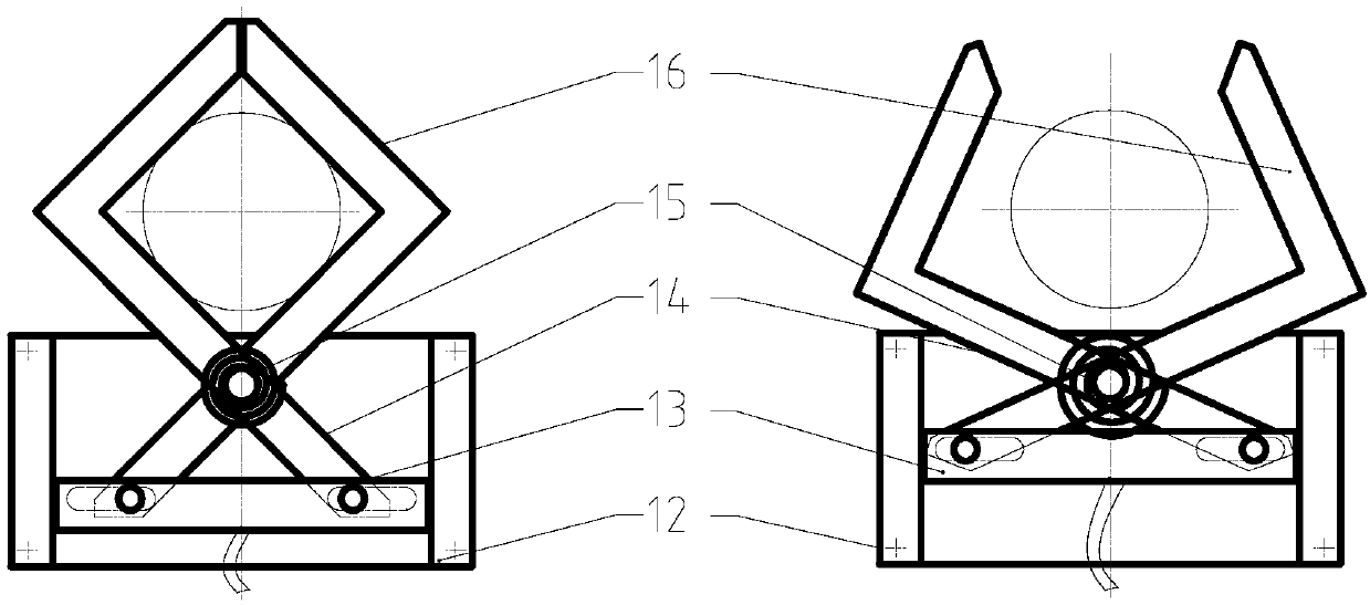
[0021] Supporting mechanism 4 comprises fixed plate 12, coupling block 13, left moving frame 14, return spring II 15, right moving frame 16, left moving frame 14, right moving frame 16, connecting block 13 are all installed on fixed plate 12, left moving frame 14 and the right movable frame 1...
Embodiment 2
[0024] See attached figure 1 , 4 , 5, the non-powered automatic clamping long bar storage device includes a fixing mechanism 1, a connecting frame 2, a linkage cable 3, and a supporting mechanism 4, and the fixing mechanism 1 includes a mounting seat 6, a return spring I7, a guide block 8, Guide rod 9, support frame 10, protective sleeve 11, guide block 8 and guide rod 9 cooperate to form a moving pair, mounting seat 6 is fixed, has a set of guiding mechanism, the upper and lower ends of guide rod 9 are respectively fixed with mounting seat 6, The support frame 10 is connected with the guide block 8 and moves with the guide block 8 . The fixing mechanism 1 has a return spring I7 , one end of the return spring I7 contacts or connects with the support frame 10 , and the other end contacts or connects with the mounting seat 6 .
[0025] Supporting mechanism 4 comprises fixed plate 12, coupling block 13, left moving frame 14, return spring II 15, right moving frame 16, left movi...
PUM
 Abstract
Description
Claims
Application Information
 - R&D
- Intellectual Property
- Life Sciences
- Materials
- Tech Scout
- Unparalleled Data Quality
- Higher Quality Content
- 60% Fewer Hallucinations
Browse by: Latest US Patents, China's latest patents, Technical Efficacy Thesaurus, Application Domain, Technology Topic, Popular Technical Reports.
© 2025 PatSnap. All rights reserved.Legal|Privacy policy|Modern Slavery Act Transparency Statement|Sitemap|About US| Contact US: help@patsnap.com


