A method for delayed generation of a check disc and its corresponding data recovery method
A technology for verifying disks and optical discs, which is applied in the field of verification, and can solve problems such as inability to use data redundancy targets and inability to modify
- Summary
- Abstract
- Description
- Claims
- Application Information
AI Technical Summary
Problems solved by technology
Method used
Image
Examples
Embodiment 1
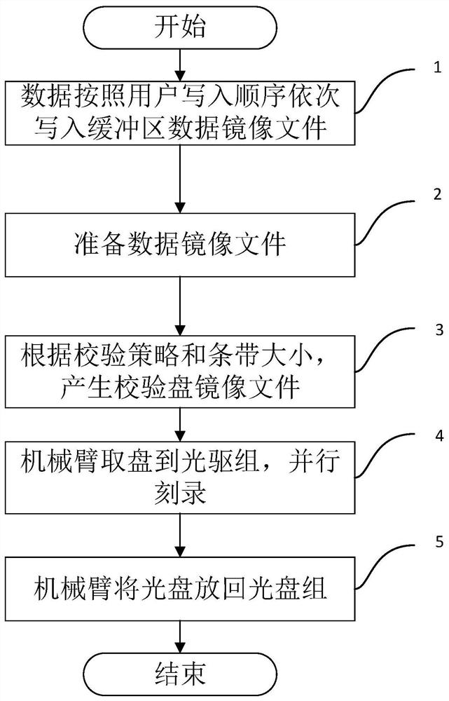
[0053] figure 2 A flow chart of a method for delay generation and verification of an optical disc provided in an embodiment of the present invention, the method includes:
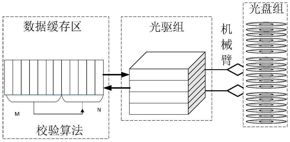
[0054] Step 1, the data files are put into the data buffer sequentially according to the order written by the user. These files are automatically assigned to logical data disk image files according to user requirements, and each image file corresponds to a binary data set burned on a physical disc, where the size of the image file is smaller than or equal to the size of the physical disc. In this embodiment, the optical disc group includes 12 optical discs, and each optical disc is 25 GB. In this embodiment, the parity check mode is selected, and 11 data disk mirror files and 1 check disk mirror file are created in the data buffer, each file is 25 GB. The data files written by the user are sequentially written to the data disk image file according to the stripe size of 64KB.
[0055] Step 2. When a set ...
Embodiment 2
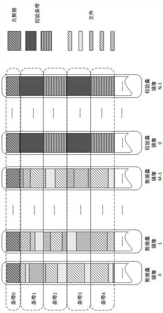
[0060] image 3 A schematic diagram of stripe verification in this embodiment is given in . For an optical disc group with (M+N) optical discs, according to the verification strategy selected by the user, it can be divided into two types of optical discs, namely, M data discs and N verification discs. For example, for a disc group containing 12 discs, the capacity of a single disc is 25GB, and the parity check method is selected, the first 11 discs are data discs, and the last disc is a check disc. according to image 3 As shown, 12 image files are created in the data buffer, the first 11 are data disk image files, and the last one is the verification disk image file. The mirror stripes are aligned according to the stripe size specified by the user. The 0th stripe stores the metadata information of the file, and the metadata stores the data or the storage location information of the file. Later, the files are saved according to the stripe size specified by the user. First, ...
Embodiment 3
[0062] Figure 4 It is a flowchart of a data recovery method provided by an embodiment of the present invention, and the method includes the following specific steps:
[0063] Step 1, the mechanical arm puts the disc in the disc group into the optical drive group. In this embodiment, there are 12 optical discs in the optical disc group, and it is assumed that part of the data on the first optical disc is unreadable. The verification strategy adopts parity, and put the remaining 10 data disks and 1 verification disk into the optical drive group.
[0064] Step 2, read the data in the optical drive group into the data buffer in parallel. Read data from 10 data disks and 1 verification disk into the data buffer image file in parallel.
[0065] Step 3, within the tolerance range of the verification data, recover the lost data according to the verification policy and stripe size specified by the user. With the parity check method, the data on one CD cannot be read, and the data ...
PUM
 Abstract
Description
Claims
Application Information
 - R&D
- Intellectual Property
- Life Sciences
- Materials
- Tech Scout
- Unparalleled Data Quality
- Higher Quality Content
- 60% Fewer Hallucinations
Browse by: Latest US Patents, China's latest patents, Technical Efficacy Thesaurus, Application Domain, Technology Topic, Popular Technical Reports.
© 2025 PatSnap. All rights reserved.Legal|Privacy policy|Modern Slavery Act Transparency Statement|Sitemap|About US| Contact US: help@patsnap.com


