Outline rendering method, device, equipment and medium
A technique of hooking lines and vertices, applied in the field of rendering, which can solve the problems of inability to render in real time and low efficiency.
- Summary
- Abstract
- Description
- Claims
- Application Information
AI Technical Summary
Problems solved by technology
Method used
Image
Examples
Embodiment 1
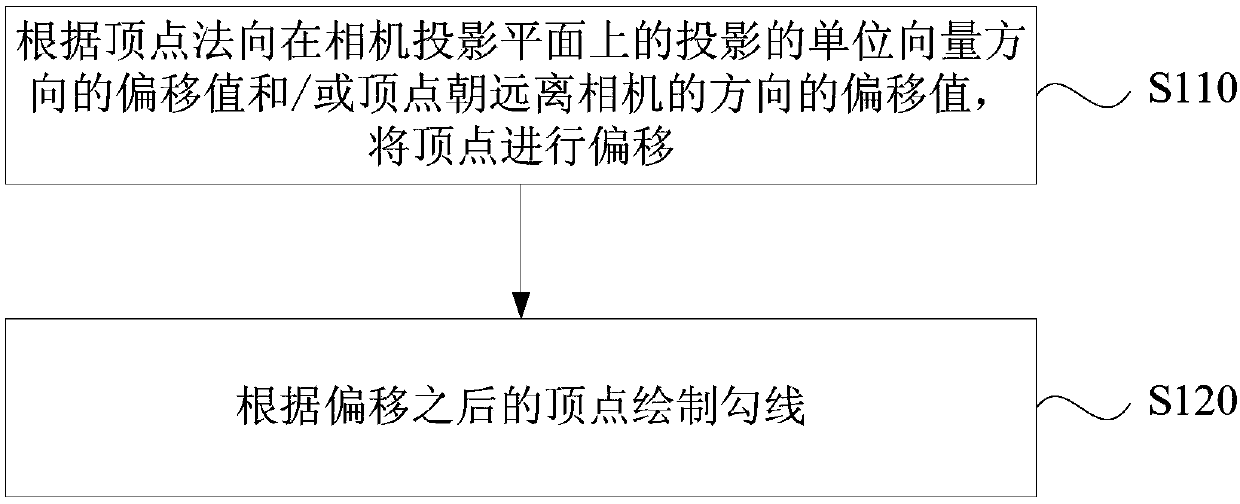
[0043] figure 1 It is a flow chart of a hook rendering method provided in Embodiment 1 of the present invention. The technical solution of this embodiment may be applicable to the case of rendering a hook line in a cartoon style. The method can be executed by a hook-line rendering device provided in an embodiment of the present invention. The device can be implemented in the form of software and / or hardware, and configured in a rendering engine for application. The rendering engine can be any smart device with a graphics card function , such as computers, tablets, mobile phones, smart cameras, etc. The method specifically includes the following operations:
[0044] S110. Offset the vertex according to the offset value of the projected unit vector direction of the normal direction of the vertex on the camera projection plane and / or the offset value of the vertex in a direction away from the camera.
[0045] Rendering is divided into front rendering and back rendering. Front ...
Embodiment 2
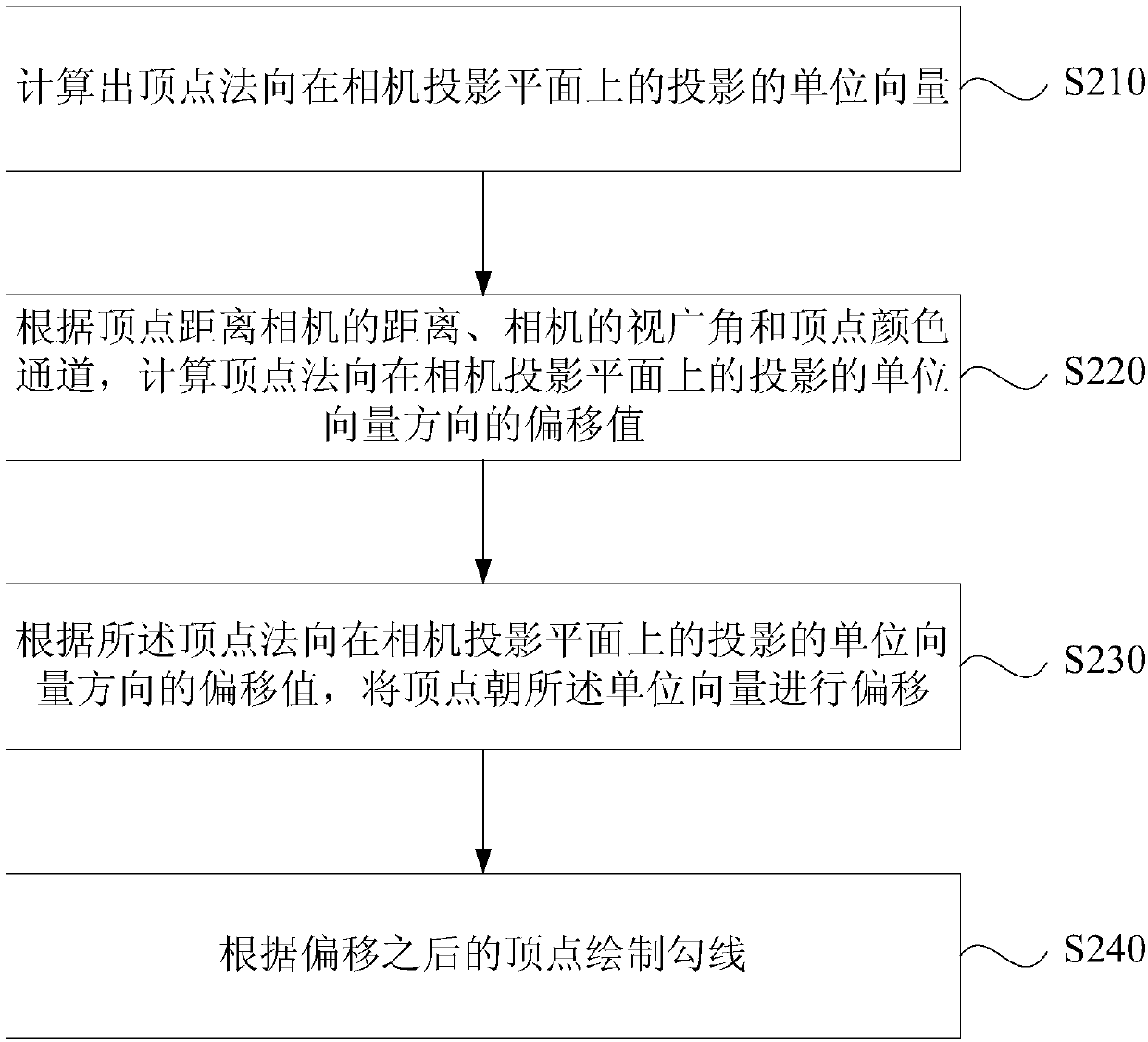
[0057] figure 2 It is a flow chart of a hook rendering method provided by Embodiment 2 of the present invention. The technical solution of this embodiment further optimizes the operation of offsetting the vertex according to the offset value of the projected unit vector direction of the normal direction of the vertex on the camera projection plane on the basis of any of the solutions of the above-mentioned embodiments. Correspondingly, the method of this embodiment includes:
[0058] S210. Calculate the unit vector of the projection of the vertex normal on the camera projection plane.
[0059] Exemplarily, the unit vector of the projection of the vertex normal on the camera projection plane can be calculated according to the calculation formula of the projection unit vector of the vertex normal on the camera projection plane: Among them, N p is the unit vector of the projection of the vertex normal on the camera projection plane, ObjectToCamera is the transformation matri...
Embodiment 3
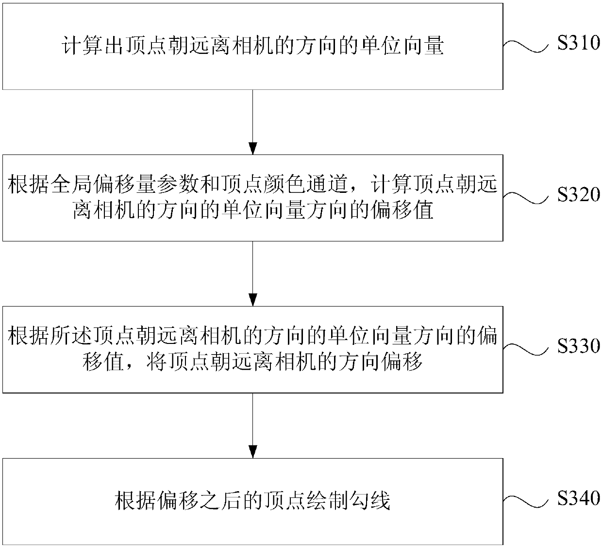
[0068] image 3 It is a flow chart of a hook rendering method provided in Embodiment 3 of the present invention. The technical solution of this embodiment further optimizes the operation of offsetting the vertex according to the offset value of the vertex in a direction away from the camera on the basis of any of the solutions of the above-mentioned embodiments. Correspondingly, the method of this embodiment includes:
[0069] S310. Calculate the unit vector of the vertex facing away from the camera.
[0070] Determine the unit vector between the vertex and the camera line according to the vector connecting the vertex and the camera, and set the direction of this vector as the direction that the vertex is away from the camera, that is, the unit vector of the vertex moving away from the camera is obtained.
[0071] S320. According to the global offset parameter and the vertex color channel, calculate the offset value of the vertex in the direction of the unit vector away from...
PUM
 Abstract
Description
Claims
Application Information
 - R&D
- Intellectual Property
- Life Sciences
- Materials
- Tech Scout
- Unparalleled Data Quality
- Higher Quality Content
- 60% Fewer Hallucinations
Browse by: Latest US Patents, China's latest patents, Technical Efficacy Thesaurus, Application Domain, Technology Topic, Popular Technical Reports.
© 2025 PatSnap. All rights reserved.Legal|Privacy policy|Modern Slavery Act Transparency Statement|Sitemap|About US| Contact US: help@patsnap.com


